Grounding and signal problems
Jul 1, 2002 12:00 PM, By John Battison, P.E., technical editor, RF
Adequate grounding means different things to different engineers. To the electrical engineer it means compliance with the National Electric Code (NEC). To the RF engineer it means proper grounding and lightning protection for all pieces of equipment connected with RF power transmission. To the audio engineer it means correct grounding to eliminate the possibility of hum or instability developing in the audio signal. Overall it also means compliance with those portions of the NEC that apply in particular circumstances, as well as individual state and local ordinances. In addition, the engineer is concerned with questions of audio quality and hum. Overriding all the considerations of audio quality and noise in the signal is the necessity for providing a safe system that is free from electrocution or burns from primary power ac, RF power or dangerous ac voltages developing in the audio equipment wiring and equipment.
I will not touch much on power engineering at this point because more and more it is becoming beyond the purview of radio engineers whose power installations usually have to be completed by state-approved and licensed contractors, and most radio engineers are not state licensed to perform such work. Sometimes this leads to problems when new installations are made that are subject to inspection by non-radio minded inspectors before completely installed, as well as afterwards. It seems that as the world becomes more and more regulated and licensed individual freedom of design and application becomes more circumscribed by political, or local union interference.
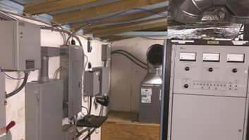
A secure and reliable ground system is a critical part of any RF installation. Photos by Ben Weiss, CPBE.


A typical argument with electrical inspectors frequently is ac power connections inside equipment cabinets. Sometimes there is a wide divergence in opinions and requirements for the location of electrical outlets inside a cabinet. This can often be a sticking point in an inspection in a large city � and sometimes even in small ones. Another argument is often the actual grounding location, and its interaction with other radio grounds.
It is best to bring the primary ac power in underground. Sometimes the power company owns the transformer and sometimes the broadcaster has to pay for it. In cases where the station is at the end of a short, dedicated line it may pay to own the transformer. This enables the broadcaster to have some control over which users are connected to his line. In any case a surge suppressor should be installed directly at the point of entrance into the transmitter building and connected directly to the system ground.
An adequate ground system is essential for any radio station. In the case of AM stations this is provided through the antenna ground system. However, sometimes this large and efficient ground system is some distance from the studio/transmitter building where the primary power ground is located. Of the station components located in the area of the antenna ground system, few are connected to the ac power line. There is usually one, however, and that one can sometimes cause problems and introduce hum in an AM signal. I am referring to the tower lighting system.
Seeing the light
The tower lighting system is tied to the antenna ground system, and it is powered by an underground cable from the transmitter building. From time to time we hear of signal interference produced by leaking or damaged components in the tower lighting system.
Examples of a poor tower ground (top) and a good tower ground. Not only is the conductor in the poor example too small, it is not attached. Photos by Ben Weiss, CPBE.


In the case of FM stations the antenna tower grounding is, unfortunately, sometimes less than adequate. Unlike AM transmitters, a large and efficient ground system is not required for FM stations, which rely on line-of-sight coverage. As a result many FM towers are grounded by a few grounding rods at the tower base. This is usually inadequate, and it is not unusual for lightning strikes to damage transmitters and associated equipment.
The damage caused by a lightning strike could be prevented by properly grounding the tower and transmission line. A few standard grounding rods connected by pieces of small-gauge copper wire will not dissipate the high current produced by a lightning strike. Before vaporizing, the small gauge copper wire will present a high impedance to the lightning that will seek an easier path, which usually turns out to be transmitting equipment. In many of the smaller FM stations, far more consideration needs to be given to FM tower grounding.
RF grounding
It is in the transmitter building and ATUs that grounding becomes of the greatest radio engineering importance. It is not just for appearance that manufacturers of phasors and ATUs lay the expensive 4-inch copper strap on top of the cabinet floors and walls to interconnect inductances and capacitors. Not only does the copper strap ensure a perfect connection between components, but its presence tends to reduce stray RF voltages from developing in cabinet sections.
The presence of a 4-inch copper strap interconnecting tower bases to the transmitter output is also important. It is not unusual in small stations, especially non-directional installations, to find that the only connection between the transmitter ground and the ATU is the outer conductor of the coaxial transmission line. Theoretically, this outer conductor will suffice to carry the currents between the transmitter and the radiating system. However, the 4-inch copper strap is needed to stabilize the radiating system and ensures an adequate connection to and from the ground system.
A continuation of this 4-inch copper strap should extend to the base of all equipment cabinets. Sometimes in high AM RF fields, a 2-inch copper strap is brought inside each cabinet to provide even better grounding connections. It is common to find a copper screen forming a Faraday shield around the transmitter, and some audio facilities are required in high-power installations located close to the antenna.
Signal grounding
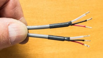
Sometimes problems arise when attempting to ground cable shields where an automatic ground is already in existence through a third grounding pin on an equipment cable. Only one end of a cable shield should be grounded. If both ends are grounded, a current will flow through the shield. If the potential difference between the two ground connections is high enough it is possible for hum to be produced.
In areas where high RF voltages are present, audio (and video) signals produce a wide variety of interference ranging from whistles to buzzes. RF interference to unshielded or ungrounded video equipment usually produces the familiar herringbone interference pattern. When investigating sources of RF interference to studio equipment it is important to confirm that the connection known as ground really is a good ground connection. This is especially true if a water pipe has been used as a ground. Hot water pipes do not make suitable grounds. It is essential to be sure that a water pipe ground is connected to ground through a metallic pipe and not plastic. The water in the plastic pipe will not substitute for a good metallic connection.
E-mail Battison at[email protected].