Our recent contribution to the Workbench column in Radio World about our home-brew construction of an XLR-3 cable tester produced a notable, positive reader reaction.
It seems almost all of us in the profession possess that “maker instinct.”
Although I’d promised in our next article to jump cold into a complex follow-up project of a step oscillator, our distinguished editors thought something as useful as the cable tester but slightly more complicated might be a better next step … sort of an organic progression.
Advancing somewhat by inculcating some simple active circuitry would also be apropos. Staying in the universe of audio, our project in these pages is an elegantly straightforward unbalanced-to-balanced audio converter.
As is often said, the beauty and joy of technical standards is that there are so many to choose from!
This dilemma holds true for the world of audio as well. We often need to make a marriage in our stations between the near-universal broadcast impedances and signal levels with the ubiquitous “consumer” output levels.
Handheld digital recorders, air tuners, computer sound cards etc. need to be taken into the broadcast plant. The situation is complicated by differences in impedances between devices, not to mention the unique characteristics of odd sources such as “pro” audio signals with their slightly higher levels.
On With the Show
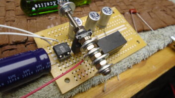
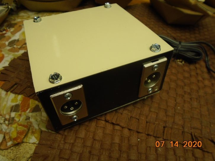
We’ve attempted to accomplish several goals here. In our example unit, we’ll use a similar enclosure to the one from our cable tester article so that, at least on our workbench, our new tools will have that matching look.
We’ll provide some flexibility in uses and setup. We’ll keep complexity and fabrication to a minimum and consequently, minimize the cost, especially as we may be making many of these.
We’ll provide enough design description and suggestions for changes and customization so you can make the project truly your own and as you need the device to work in your plant
Let’s get oriented. A parts list for this project is at the bottom of the story.
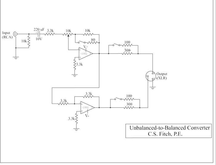
First take a look at the schematic at top.
Addressing just levels, consumer audio from something like a CD player is expected to peak at 0.447 volts with an RMS (Root Mean Square) value of 0.316 volts, which is well within the handling capability of an operational amplifier (op-amp).
If our audio is headed to a typical 600-ohm standard broadcast mixer input of +4 dBm, the level at that point will need to be a peak of 1.736 volts or 1.228 volts RMS. As such, the RMS voltage gain will need to be about 3.9, or 11.8 dBV.
Circuit Details
Like most electronic circuits, one can generally divide the beast into main activity and support sections. The main in this case is the signal flow area; the support is essentially the power supply, connectors and enclosure.
Start with main. In our circuit, the unbalanced signal enters the converter and encounters a 10k ohm shunt resistor to ground, which is included as the industry-suggested load impedance that provides the flattest signal response transfer. The 220 uF series capacitor isolates the audio, stabilizing the gain of the first active stage to follow.
The op-amp sections in this device are configured in the inverting format, providing great flexibility and stability.
Many readers will remember that most of my previous audio processing work in these pages used the classic 1458 op-amp, as I had been given and used over 100 of them. Now that I’ve been given an even larger number of the similar but higher performing 5532 op-amps, we’ll start using this new group to a similar depletion.
The 5532 is a self-compensated, dual-section unit. The first op-amp section provides two functions for us. The first is gain, and with that in mind, our required gain might be that voltage gain of 4 noted above to achieve line level output, but could also be a negative gain to help us get down to mic level.
To Invert or Not to Invert
A fundamental facet of a non-inverting op-amp (the alternative arrangement of the inverting circuit configuration used herein) is that one cannot achieve negative gain, which is gain less than 1. The inverting configuration, used here, can accomplish negative gain similar to an attenuator.
The second purpose of this stage is to create one of the two output lines of our active balanced output. As our op-amp is inverting the input signal, the AC audio voltage here would be the inverse polarity of the input. So, we have marked the line – (negative).
The complimentary output line (+) is generated by the second of the IC sections configured once again as an inverter.
We need the mirror imagine of the other line, so we invert with a gain of one. A gain of one is achieved by using the same value of resistors in all positions. Incidentally, the value annotated on our schematic of three 3.3k was determined by the circumstance of being given over 100 3.3k resistors via the largess of a generous friend and that these 3.3k’s were 1% tolerance. This close resistance matching is quite helpful in achieving that perfect gain of one if you’re a real op-amp purist.
One can use three of just about any value, but something between 1k and 10k, at least in my experience, seems to work best.
As noted, we have created a very usable balanced output with the two op-amp sections.
A fundamental characteristic of all op-amps is a very low output impedance such that these active devices approach being a perfect current source.
The author has been blessed with a great number of knowledgeable and generous instructors, and I’ve honored them often in these pages. From the wisdom of my mentors has come a world of wise words. One of my favorite quips, on this very subject, is: “Because of that low impedance, an op-amp can almost drive anything right down to a short … if there is even a little bit of resistance in that short.”
With this in mind, to create a source impedance for best and flattest power transfer, we insert resistors in each of the output of these op-amps to match the impedance of the input to follow, hence, the 300 ohm resistors in the + and – sides, which provide a 600 ohm source. Shunting these individual resistors with 100 ohms results in 75 ohms on each side, dropping the source impedance to 150 ohms and mimicking a mic output.
Flexibility
The changing of the output resistance between these two choices is accomplished by a DIP switch on each resistor. Another DIP switch changes the gain from a nominal 10 dB to –40 dB, bringing the output level down to about microphone level.
The gain of an inverting op-amp is set by the relationship of the input and feedback resistors. The 10k 20-turn trimmer fine adjusts this relationship, pretty much allowing you to land the gain (and maybe even the fader position) exactly where you want it.
Bench testing indicates that my finished version has a remarkably flat frequency response. The value of the input cap was chosen to improve/maximize low frequency coupling. THD was excellent with the worst case no higher than 0.4%.
The abundance of 0.01 uF caps are just good engineering practice and, once again, enabled by being given a big bag of beautiful 50-volt mylars. (Buc, don’t you ever have to buy anything?)
If full isolation of the output is needed, a transformer can be connected to this balanced output, and a typical transformer with nominal 600 ohm impedance on each side is listed at the end of the parts list.
Power Supply and Other Support Items
Most audio sources in one’s radio station in 2020 are stereo, and so for that reason, our constructed box has two channels.
We’ve chosen to use a wall-wart from the salvaged/harvested box of about 8 volts DC output as our power source. Anything between 8 and 24 volts should work. This DC could be applied directly to the 5-volt three-terminal regulator, but since the power might come from an AC or reverse polarity source in the future, a bridge rectifier was included. If away from hard power, one could even use the DC from a 9-volt battery as a power source. Using this scheme, one has infinite options.
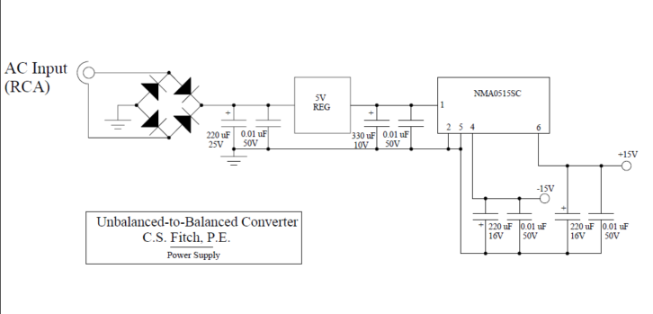
If you’re permanentizing your converters, a transformer with simple regulator circuit is located in an isolation box at the lower corner of the schematic as an alternative to the above concept.
A DC to DC converter follows and that takes the regulated 5 volts in and converts this to + and – 15 volts for use by the op-amps. The particular converter chosen has 33 mA capability for each rail, which is more than adequate. In development, the worst-case current demand noted was about 8 mA for each 5532.
The + and – 15-volt operating point is a foible of the author as it seems to me to produce a slight but measurable improvement in S/N. Further, this 30-volt differential easily allows a +10 output if needed.
The abundance of 0.01 caps are for RF elimination. They also reduce any penchant for oscillation along the power supply rails.
RCA (phono) connectors were used on the unbalanced side as this is the industry standard. XLR-3 males were used on the output in anticipation that we will be using high-level broadcast inputs primarily.
The parts list is below; click on it to download in a Word doc.
Now that you have the “big picture,” it’s up to you to build one that is flexible, custom, useful and reflective of your own genius.
Charles “Buc” Fitch, P.E., has been a consulting engineer for 40+ years. He is a senior member of the AFCCE and SBE; holds SBE CPBE with AMD certification and electrical contractor licenses; and is a former radio station owner and TV DOE. He is a past recipient of SBE’s Writer of the Year and Educator of the Year awards.
Comment on this or any article. Email [email protected] with “Letter to the Editor” in the subject field.
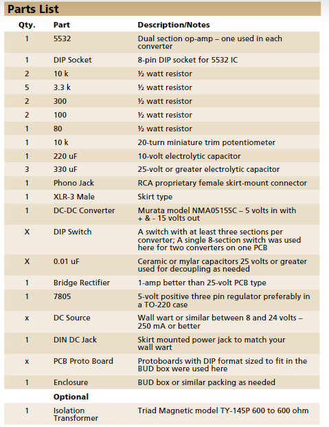
Parts List for Unbalanced to Balanced Converter Project (click for text version)