A young chief engineer who knew a lot more about computers than transmitters and analog audio systems recently asked me for help in tracking down on-air distortion that had affected his mom-and-pop station for some time.
The station did have on-air distortion. It was not terrible, just bad enough to notice, though the longer you listened, the more it irritated — a real turnoff for Time Spent Listening.
It sounded to me a bit like the audio was going through an amp with bad power supply filters, and it had a raspy edge on voice. But identifying the source of the problem by ear was difficult.
This was an AM station that had an FM translator mounted on the hot tower, a situation that can present its own set of challenges. The distortion was evident on the FM. But a critical listen revealed that it was present on AM as well!
This pretty much ruled out my thought that high RF at the tower was being rectified on the audio input to the translator and showing up as audio distortion. So it was time to take a look at the audio chain.
Clamp!
Pretty straightforward: Program was being delivered from the studio miles away, with digital uncompressed audio sent over fiber. It sounded good going in, and it sounded good coming out. Yet the on-air product definitely was distorted.
The audio was fed to the FM via a buried 1,000-foot cable to the tower. That line was driven by a pair of old super-quality Western Electric 111C repeat coils set up for 600 ohms in and 600 ohm line out with center tap grounded — the perfect way to send audio in an RF field. This arrangement no doubt had been set up by a previous chief who knew the magic of repeat coils for long lines.
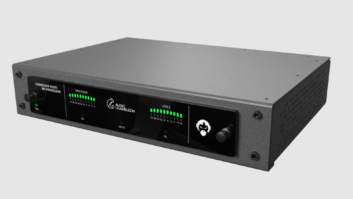
Audio from the codec was connected to a Broadcast Tools switcher, then to the program line that fed the AM processors and the FM line to the tower.
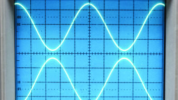
I grabbed a handheld oscilloscope — something the young chief had never seen — and pulled the output connector from the switcher. I gave it a look on the scope with a 600-ohm load, and it showed nice clean peaks at about +8 dBm — looked good, sounded good.
I plugged it back in and bridged the line with the scope. Aha! The scope showed clipping with the peak levels closer to +3 dBm and a definite ceiling.
There was trouble here, but why?
Audio level on the coils was well under the +30 dBm (1 watt) design limit for the rugged four-pound 111Cs.
Still searching for the problem, I spotted a couple of black boxes where the cable leaves the building. These were Grommes~Precision TLS lightning suppressors.
When I looked up their data sheet, things started to make sense.

The TLS contains multiple stages of lightning protection. This unit is designed for protection of audio paging circuits with an RMS audio level of 1 volt. On a 600-ohm line, 0 dBm (1 milliwatt) is .774 volts, so with a level of +8 dBm (1.94 volts) the line level was crossing the clamp point for the TLS.
While the spec sheet shows a switching to ground level of 25 volts, the unit starts clamping just over one volt.
Us old guys
While finding this problem was a bit of a challenge, fixing it was a snap. With the drive to the line reduced to –3 dBm (.5 volts) on the PPM meter, things sounded great.
Another solution would have been replacing the TLS units with LLS models that have a pass rating of 6 volts (17 dBm), which is better suited for broadcast levels. But we work with what we have.
Now you might ask, why did the AM sound bad if the problem was on the FM stereo pair?
The Broadcast Tools switcher derives its mono output (used by the AM) by passive combining of L+R internally from the stereo output. So if the stereo line gets clamped, so does the mono line!
I suggested and installed a set of 1000-ohm buildout resisters on the output of the switcher, the better to isolate the FM feed, just as a precaution. With the 111C coils set up for center tap ground, the TLS might not have been needed at all; but better too much protection than not enough.
With the elimination of the distortion, the station was able to process a bit harder, increasing the loudness while improving the sound quality — a win-win for sure.
While I was there I couldn’t resist teaching my young friend to reduce the AM modulation peaks from 130 percent positive (yikes!) 100 percent negative, to about 90 percent symmetrical. He heard the difference and agreed to keep it that way.
The takeaway here is simple: Read spec sheets, and know how adding devices will affect your overall sound.
My assist call also underlined a growing problem in broadcasting. “Us old guys” know analog audio and issues peculiar to AM. The new “engineers” are not getting that knowledge, learning only about digital and computer networks. I hate to say it, but institutional knowledge is dying as more of us become silent keys.
Solution? Us old guys need to take every opportunity to reach one, teach one.
The author is chief engineer and owner of WGTO Cassopolis, Mich., and W246DV South Bend, Ind. Read more of his past articles.
Share your own tech tips or stories about how you solved a problem. Write to [email protected].