BOSTON Now more than ever, broadcasters need to make sure their transmitter facilities are in good shape.
While it is true that over the years there has been a dramatic improvement in the efficiency, ease of service and reliability of RF transmission equipment, the pool of experienced RF engineers has substantially decreased. Many new engineers today may not have had a chance to work in high-power RF plants.
Many older engineers are reaching retirement age; but more significantly, young men and women entering the field are more geared toward the information technology/computer side of radio engineering.
Why not? The line between computers and transmitters is becoming less defined each day. Most radio transmitters manufactured during the previous two decades contain some kind of microprocessor or in some cases are full-blown personal computers.
With the advent of HD Radio, this has become particularly true. In this age of computerized broadcasting, it is vital that we not lose sight of some of the basic engineering principles and standards.
Keep it clean
Keeping a transmitter site clean and organized has many benefits.
It is usually beneficial to employ a redundant closed-loop HVAC system to keep dirt, pollen and humidity out of your shelter.
Transmitters that operate with high voltages especially will benefit from the clean environment because high voltage tends to attract dirt and can lead to unwanted arcing. Proper air flow in transmitters, audio processing gear and computers is also critical; and dirt and pollen can quickly clog air filters leading to overheating of components and eventual failure of critical systems.
In addition, having redundant HVAC systems helps to assure that unattended transmitter sites will continue to stay cool if one of the air conditioners were to fail, until repairs can be facilitated. It’s now common to install a tertiary ventilation system that will simply bring in filtered outside air and draw it across the room to cool the area in the unlikely event that both HVAC units were to fail.
An ideal transmitter facility will have redundancy for most of the equipment. In many cases the costs associated with buying “two of everything” are impractical.
If you are able to duplicate equipment, one strategy that has proven to increase overall reliability is to have a main and an alternate “chain.”
A facility in which each transmitter is fed by its own set of processing and STL path helps to ensure that in the event of a problem (i.e., RF off the air, audio off the air or audio problems like distortion etc.) you have the best chance of bypassing the problem as quickly as possible until the problem can be addressed by simply switching to the alternate transmitter chain, including the RF amplifier.
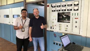
(click thumbnail)Fig. 1: Portable Sony LocationFree TV Web browser is used for data entry into the electronic maintenance logA “main/alternate” configuration implies that both systems are close to being equal in terms of reliability and quality. An ideal main/alternate configuration will be run on a regular changeover schedule.
Depending on your individual circumstances the times will vary; a popular method is to alternate systems on a quarterly basis. This helps prove to yourself that both systems are working properly; in the event of a failure on any one system, you will be confident that you can switch reliably to the alternate system and your business will not be compromised.
If you have a primary/backup system, your backup transmitter may not be as modern and therefore may not offer you the efficiency and reliability of your main transmitter. It is extremely important to test it regularly and maintain it as well as your primary.
Safety
Often, preventive or required maintenance is performed on transmission gear that has lethal voltages inside. While all manufacturers of modern broadcast equipment take precautions to interlock their equipment when a door or access panel is removed, occasionally it is necessary to bypass these safety measures in order to troubleshoot the problem.
When this happens, the engineer opens himself or herself up to added risks. The consequences of making a careless mistake can be deadly. Compounding the problem is the fact that many of these maintenance sessions are performed late at night at a time when the engineer may be fatigued, and could carelessly make a mistake.
The issue is a serious one, and requires one carefully to manage the risks associated with transmitter maintenance. Some of the tools available to the engineer to lower this risk include using checklists, making sure the shorting stick is used before contacting any potential high-voltage points and never working alone.
The equipment itself needs to also be protected. If you employ an air-cooled dummy load, make sure that it is interlocked to remove the RF source from whatever transmitter is connected to it, should the cooling fan in the load fail to operate.
The same is even more relevant with a water-cooled dummy load. If sufficient water flow is not maintained, the load element will be destroyed in a matter of seconds. A properly adjusted, high-quality external water flow switch is usually required to protect a water-cooled dummy load.
(click thumbnail)Fig. 2: Completed maintenance log in loose leaf notebook at transmitter facility
Just as the load needs to be protected, those who use a manual or motor-driven RF transfer switch need to make sure that these switches are interlocked to any transmitters to which they are connected. Usually moving an RF contactor with RF present can cause serious damage to the switch.
Probably the most important — and unfortunately one of the most widely overlooked — interlocks needed at transmitter site are the VSWR protection interlocks.
Even though modern transmitters provide internal VSWR fold-back protection, it is absolutely necessary to have an external VSWR meter capable of interlocking the transmitter(s) installed at an appropriate place in the transmission line system, and tested on a regular basis.
The cost of installing and maintaining such a device is a small insurance premium to pay for a whole lot of protection afforded to your expensive transmission line and antenna system.
Another vitally important consideration for those using transmission lines with an air dielectric is proper pressurization of the transmission line system with dry air or an inert gas such as nitrogen. The object is to keep the voltages between the inner and outer conductors of the transmission lines from arcing over and destroying the line.
Using a dehydrator to dry the air to a very low dew point guarantees that the moisture content in the line will be low enough to avoid arcing.
The other popular method that is effective is to infuse the line with nitrogen gas from a bottle or a nitrogen generator. This effectively removes any moisture in the line and helps to prevent flash over.
Having an electric pressure switch to monitor the transmission line’s gas pressure and relay the status to the operator on duty is imperative so that if an air leak develops, it does not go unnoticed.
Finally, for air-cooled tube type transmitters a routine testing program for the air flow safety systems is important. Even though all tube-type air-cooled transmitters employ a safety air flow switch, unless they are tested on a regular basis you can’t know whether they are actually working to protect your equipment.
One popular method is to slowly restrict the air flow to the intake filter with a piece of cardboard on the transmitter under test until the air interlock is no longer satisfied, and verify that the filament gets turned off.
Most tube manufacturers furnish a data sheet that along with specifications for operating parameters depicts recommended filament voltage settings. Typically it is advantageous for a brand-new tube to be run at the rated filament voltage for the first several hundred hours and then at a reduced voltage for the life of the tube.
Eventually when the emission drops off the voltage can be increased to a certain point to extend the useful life of the tube further.
Transmitter maintenance logs
Running your transmitter facility efficiently and with a minimum amount of down time requires good record-keeping. Most engineers accomplish this with maintenance logs.
These records help keep an accurate record of service to equipment, as well as regular records of calibrations. Perhaps the most useful aspect is the fact that engineers can refer to a record of what normal parameters are, and thereby easily understand how trends in parameters are affecting the operation.
With the availability of smaller computers and PDAs it is now practical to record and analyze maintenance log data electronically. This has a few advantages over the paper method.
For example an engineer using a portable electronic device such as a laptop computer, PDA or other handheld Web browser can directly input information read from the equipment meters for accurate storage, and later retrieve that information. Advantages over the paper method are:


- The data is stored in a logically formatted structure and is easy to read.
- The data can be easily manipulated and sorted by field
- It becomes apparent when trends in readings start to occur and an engineer can more quickly take action to address any equipment shifts in performance.
- Maintenance logs can be printed out in a uniform way with color coding and different sizes of fonts to highlight changes the engineer might want to be aware of.
- Maintenance logs can also be posted to an internal or external Web page so that it is possible to access the data from many locations.
- Log fields can be individually sorted by value so the person analyzing the data can see the highest or lowest value in a field.
- Comment fields in logs can be sorted by keyword. For example, search the comments field for the last time a tube was changed.
- Mathematical calculations can be routinely done to calculate a running time tally on items such as the time between tube changes in a particular transmitter, or elapsed run time of a dehydrator.
Web access
Even when you are not at the transmitter site, if you write these logs to a Web page it gives you the flexibility to access maintenance data from anywhere.
This allows an engineer to more thoroughly analyze the historical data in a cleaner, quieter and often more relaxed atmosphere (like the office or home) where he or she can spend more time looking at trends and understanding the changes that might be occurring at the transmitter site.
(click thumbnail)Fig. 3: Web Page with log
In Fig. 3, the Web page shown uses a Java Applet to enable the user to sort the individual fields by value.
It is also becoming more important than ever to supply good, clean and uninterruptible AC power to the equipment at your transmitter site.
In particular, transmitter sites often are located in remote areas where utility power is not the most reliable; physical access to the site can be restricted by weather conditions or other environmental factors.
Since almost all the gear used these days is CPU-based, a power glitch will end up resetting most equipment used at a transmitter. Most equipment does not reset instantly, and will normally take a minute or two to come back to life. This always seems like an eternity when you are off the air.
Finally, the Federal Communications Commission and Federal Aviation Administration recently have modernized the rules regarding tower sites.
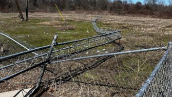
Make sure that the base of the tower and guy wires are secure, and that the tower registration number is displayed prominently not only at the tower base, but at a point that can be easily seen from the street (or a public point) leading to the tower.
Tower light monitoring remains one of the more important rules that the FCC is enforcing. A system must be in place to allow your operators to detect a full or partial failure of the tower lighting system immediately.
If your tower lighting system is not operating as specified in the station’s authorization, notification to the FAA (through a special toll-free number) is required within 30 minutes. Notification is required again when the problem has been resolved and the lights are operating in accordance with the station’s license.