Tom Ray Offers a First-Person Account of Going Digital at the Legendary Station in New York
NEW YORK While we’ve all heard and seen things regarding in-band, on-channel digital transmission for AM and FM stations, there hasn’t been much written in regards to what it will take to install IBOC on an existing facility.
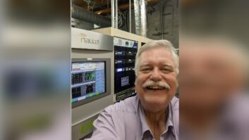
WOR(AM), a 50 kW flame thrower in New York City and one of America’s pioneer broadcasters, became New York’s first digital AM radio station at 9 a.m., Oct. 11.
First and foremost, before you delve into the world of IBOC, you must first evaluate your transmitter facility. You may have seen articles regarding what you need to do in order to make your facility IBOC-ready.
Would it be nice to have all digital studios and a completely digital studio-to-transmitter link to make this happen? Sure. Is this practical for most stations? No.
Most of us need to live within a budget, and replacing the entire plant, microphone to antenna, makes no sense initially.
Because this article focuses on the transmitter plant, I’ll say only briefly that WOR has older studio equipment: our consoles are literally serial numbers 1 through 5 of Pacific Recorders & Engineering’s System 1 console, the predecessor to the BMX, and are mono. We will concentrate on our studios in the next two or three years, and made no changes at the studio with the exception of our monitoring situation, as IBOC introduced an 8.5-second delay into our analog audio.
Plant ready?
WOR’s transmitter facility has seen much work over the past five years. It started with a rebuild of the phasor and coupling circuits for our three-tower dogleg array. But this is not just any three-tower dogleg.
The transmitter plant is located in Lyndhurst, N.J. The area is an RF oasis. On our street, all within 1-1/2 miles of each other, are WOR(AM); WLIB(AM), New York; WJWR(AM), Newark, N.J.; and WINS(AM), New York.
Counting WOR, there is approximately 300 kW of RF over our site. You can shut off WOR’s transmitter, ground a tower and draw a considerable arc. We have almost 3 V/m at 1010 (WINS) alone.
Needless to say, our antenna system consists of detuning skirts on the towers to electrically shorten them at 1010 and 1190 kHz, detuning networks at the bases of the towers for 620, 1010 and 1190, traps for 620, 1010 and 1190, and then we actually get to the components that WOR can use.
The redesign, performed by Carl T. Jones Corp., took WOR’s common point, which looked like a rollercoaster on either side of 710 kHz, and made it fairly flat +/- 15 kHz from carrier. After that, the common point impedance goes to hell in a hurry, but for IBOC operation, your antenna and/or common point should look fairly flat and the reactance flat or at least symmetrical over the passband of +/-15 kHz from carrier.
WOR passed the first major test.
You next need to look at your transmitter. According to information I received from Harris at its IBOC road show, a tube-type AM transmitter pretty much will not have the stability required for the phase modulation components of the IBOC signal. The RF chain needs to be fairly linear, and, in the case of a pulse duration modulated transmitter, the sampling frequency needs to be high enough and the filtering broad enough to allow the IBOC components to properly pass through to the final amplifier.
WOR uses a Harris DX-50 transmitter for a main. The unit is basically plug-and-play for IBOC. Our older auxiliary transmitter, a Continental 317C-1, pretty much doesn’t have a prayer of passing IBOC, though both Chief Engineer Kerry Richards and I think it might be interesting to try IBOC on the beast to see what would happen.
As WOR had a main transmitter that is more than capable of passing the IBOC signal, and the antenna system looked good, it was time to play.
Installation
Kerry and I prepared the site before Pat Malley, a field engineer for Ibiquity Digital Corp., arrived one fine Sunday afternoon for installation.
To get the IBOC signal into the transmitter, an interface box needs to be installed between the exciter and transmitter. The connections between the interface and the transmitter are a BNC for a coax connection to the external RF input and a Phoenix-type connector for the audio connection. As an option, there is a control voltage input that can be paralleled to a relay in the transmitter to change between internal and external excitation.
Connection between the exciter and interface is done with Cat-5 cable. I can now say that I have pretty much seen it all – I have connected my first 50 kW AM rig using shielded Cat-5 cable. Before Pat arrived, Kerry and I had run the Cat-5 from the racks to the transmitter, and made sure we had jacks available on the patchbay for input to the A/D converter. This took about an hour.
Pat arrived bearing gifts, and we put the auxiliary on the air. We proceeded to connect the Cat-5. Kerry worked on getting the connections between the patchbay, A/D converter, exciter and processing correct. I installed the bypass relay in the DX-50, changed the audio input and installed the BNC cable for external excitation.
We brought the DX up into the dummy load at 5 kW. We made sure that when the exciter was in the bypass mode we were, in fact, operating on the internal oscillator and, when not in bypass, we were operating on the external excitation from the exciter.
We then needed to set up the internal AM reference in the exciter. This was done by putting our Optimod 9200 into test tone mode and watching the reference signal from the exciter on a scope. We set the exciter for 100-percent negative modulation, then fired up the DX, with the IBOC carriers off, and adjusted the gain on the interface box to produce a 100-percent modulated signal into the dummy load. So far, so good.
Next, we turned on the IBOC carriers with the transmitter set for 5 kW. The display on the spectrum analyzer looked good, but on the receiver, the audio sounded awful in digital and in analog. It was time to troubleshoot.
Turns out the analog-to-digital converter between the STL switcher and processing was bad. A quick replacement of the A/D resulted in clean audio.
Several adjustments need to be made on the IBOC exciter during installation. One major adjustment sets the phasing delay of the IBOC waveform as it passes through the transmitter. (From AM stereo, remember setting the group delay through the transmitter?)
This is done by making an adjustment on the touchscreen of the IBOC exciter while monitoring data errors on the receiver, or by watching the RF signal on a spectrum analyzer to minimize “spectral re-growth” around +/- 20 kHz from carrier. I’m happy to say that errors on the WOR signal are zero and the signal is extremely stable.
The next alteration was to adjust the delay of the analog signal to match the delay of the digital signal precisely. The reason for this adjustment and the delay added to the analog is that the radios are designed to lock on a station in analog mode, then, when the digital signal is acquired, blend or crossfade into the digital signal.
Obviously, if the two signals are not time-aligned, the listener will hear an abrupt switch between them. Additionally, the radios are designed so that, if the digital signal is lost, the radio will immediately revert back to the analog signal. Once again, if the signals are not time-aligned, the change will be abrupt.
The easiest way to time-align the signals? We set the receiver to produce the digital signal on the left, the analog on the right, and proceeded to match them by ear! The result is that there is no abrupt change when the receiver blends.
We then brought the DX up to 50 kW. All the above tests were done at a lower power level so that the dummy would not get grumpy and take up smoking. Analog sounded really good. Digital, because the processing is very light (as opposed to our analog which is very “in-your-face”), sounded close to FM quality.
Then … glitch!
The DX-50 reduced its power to 25 kW, and ramped back up to 50 kW. We thought the problem might be that the dummy, which admittedly needs some work, was shifting impedance, so it was time to put the DX-50 back on the air.
On-air testing
We switched back to the DX-50. It sounded really good in analog. We turned on the IBOC carriers. It sounded wonderful in digital. Then … glitch! The DX abruptly dropped to 25 kW, then ramped back up to 50 kW.
It became obvious the dummy load was not the culprit causing the glitching.
It did this several times. Pat said he had seen this before.
A call to Harris showed that, on the bandpass filter VSWR monitoring, the voltage and current sample points are taken in different locations along the circuit. At some point during operation, the zero crossing points of the voltage and current due to the phase modulation of the transmitter must occur at the same moment in time. The VSWR circuit takes this as a problem in the bandpass filter, and reduces the transmitter’s power for protection.
As a Band-Aid, per Harris, we have bypassed the bandpass filter VSWR circuit. Harris is working on a field modification that we will need to perform on our DX-50 in the near future.
Total time spent? About three hours, and IBOC is on the air.
Results
Of course, Kerry and I rushed to our cars to see what the outcome was on the air. My car has a stock Ford AM stereo radio. Kerry has a high-end radio with a $2 AM section.
Before Ibiquity arrived for installation, we had reset our Optimod 9200 processor from its NRSC settings to a 5 kHz brick-wall rolloff. We based the 5-k setting on our NRSC processing settings and added our own EQ curve.
Listening on our car radios, we could barely tell a difference in the processing changes on the AM stereo radio, and could hear no difference at all on the high-end radio. Because we’re not modulating above 5 kHz, we are now louder on these radios than we were.
Once IBOC was on, we listened for artifacts. On the supposed “wideband” AM stereo radio, I need to turn the volume up to ear-splitting levels before I can hear any noise under the audio. On Kerry’s radio, you cannot hear any artifacts of IBOC whatsoever.
WOR’s listeners are a loyal and vocal bunch. If they hear something wrong, they do not hesitate to speak up and make it known that “their” radio station has a problem and they want it fixed N-O-W. Our calls from listeners have consisted mostly of people wanting to know how they can hear our digital signal and where they can buy the radios.
We have had a few complaints. One was from a gentleman who was restoring a 1930s vintage Atwater Kent radio, and wanted to let us know he heard hiss when he tuned across WOR on either side of us.
Negative comments also have come from a group of AM stereo fanatics in New Jersey. These people live for the day AM stereo makes a comeback. They are not listening on typical AM radios. They have verbally and personally attacked both Kerry and me, as well as the radio station and Ibiquity.
This group thinks that AM radio is a high-fidelity medium. They also started a rumor that WOR was operating illegally. The NRSC mask allows emissions to -25dBc from 10 kHz to 20 kHz. IBOC operation puts the IBOC carriers from 5kHz to 15kHz at -30dBc, perfectly legal.
The other complaint was from a person who was trying to get WLW(AM). This person lives not all that far from our transmitter. Unfortunately, the IBOC carriers occupy space in the NRSC mask around 700 kHz, and the listener was not able to DX in the near field of the WOR antenna. But because WOR is operating legally, there is not much that can be done for this person.
The spectrum on the WOR signal basically was textbook-perfect. The entire signal fits nicely under the NRSC mask and is completely legal. Even with all the detuning aspects of WOR’s antenna, the IBOC carriers are symmetrical.
IBOC was installed without rebuilding our studios or replacing our STLs. The time spent for installation was about three hours, and we did it in the afternoon with the auxiliary transmitter on the air.
If your antenna system is in reasonable shape, and your transmitter is of fairly recent vintage (i.e., not a 1955 BC-5P), you should lose little time and spend the minimum amount of money putting IBOC on your AM station.
For more information, I recommend Ibiquity’s Web site at www.ibiquity.com. Or call your favorite RF supplier. Ours is Harris, which can provide you with details from their IBOC road show, and guide you as to whether your IBOC installation will be as uneventful and easy as ours was.
WOR also has a section of our Web site dedicated to our IBOC installation, and information is added as we receive it: www.wor710.com/Engineering/iboc/hdindex.htm.