You Can Takes Steps to Protect AM Antennas Against Reradiating Structures
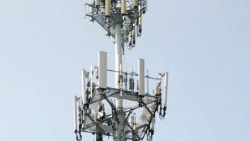
With the continued growth in the wireless communications industry, the demand for better coverage requires more and more antenna support structures.
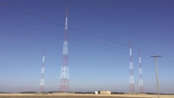
While most such structures are electrically short at AM broadcast frequencies, they can be remarkably efficient radiators. If located in an area of high incident field from a nearby AM station, substantial amounts of reradiation can be produced. This can significantly distort the circularity of a non-directional radiator, or distort the pattern and fill the nulls of a directional array, causing the station to exceed the licensed radiation limits in certain azimuths and produce interference to other stations.
It is the responsibility of the structure owner to ensure that no significant reradiation occurs; but in the end, it is incumbent on you, the AM station licensee, to protect your pattern.
Protection
47 C.F.R. §22.371 provides for protection of AM broadcast station antenna patterns by Public Mobile Service licensees such as cellular that construct or modify antenna supporting structures in the immediate vicinity of AM broadcast station antennas. Similarly, 47 C.F.R. §27.63 provides for protection of AM broadcast station antenna patterns by Wireless Communication Services licensees.
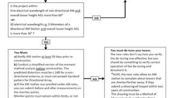
Boiled down, these FCC rules require that licensees constructing or modifying such antenna supporting structures must take certain steps if the structure falls within 1 km (0.6 miles) of a non-directional AM station or 3 km (1.9 miles) of a directional AM station. The licensee with an antenna structure that lies within these boundaries must prove scientifically that the construction or modification has not affected the AM station antenna pattern.
The procedure for determining this includes two sets of partial directional proof-of-performance measurements, made in accordance with 47 C.F.R. §73.154.
The first set, made pre — construction or pre — modification, establishes a baseline. It is not necessarily intended to show that the AM station is operating within the terms of its license. The second set of measurements, made post — construction or post — modification, is analyzed and compared to the pre-construction or control measurement set to determine what, if any, effects that the construction or modification has had on the radiation pattern. The details of the exact measurement procedure are discussed below.
Uncertain results
In a perfect world, an entity constructing or modifying an antenna supporting structure would make the required pre/post measurements, analyze them and conclude that the structure has had no effect on the AM station’s pattern. The documentation would be presented to the FCC and to the AM licensee and all would be satisfied.
In the real world, however, quite often the measurement results are either ambiguous or inconclusive. In many cases they show that the structure produced some effect on the AM pattern but did not cause it to exceed the standard pattern value along any azimuth; the AM station, though its pattern was affected slightly, remains within its licensed limits.
The trouble with an AM licensee blindly accepting such a situation is that this pushes him ever closer to the point where he is not in compliance. An otherwise small environmental change, seasonal variations in ground conductivity or small drifts in pattern parameters may cause a violation.
This fact indicates that a greater level of vigilance is required of AM broadcast licensees and their engineers. In the end, it is the AM licensee that will be left holding the bag. Because the danger here is primarily to AM stations employing directional antennas, we focus here on such stations.
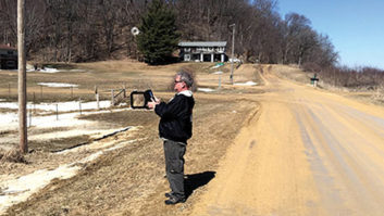
47 C.F.R. §73.154 specifies the procedure for making partial directional proof-of-performance measurements on AM antenna systems. In short, at least eight measurements must be made between 3 and 15 km from the center of the array on each monitored radial.
In the case of simple arrays with fewer than four monitored radials, measurements must also be made on the radials from the latest full proof-of-performance adjacent to the monitored radials. The measurement locations selected must be from the latest full proof-of-performance.
Measurement locations must be unobstructed, i.e. clear of overhead wires, metal structures and the like. A good rule of thumb is that as the field intensity meter is rotated, there should be at least a 10-to-one ratio between maximum and minimum signal. Anything less indicates local reradiation and the location should be rejected.
Same parameters
Before each set of measurements is made, determine that the operating parameters are correct, either at the licensed values or within the licensed limits. In some cases, a station normally may operate at variance with the licensed parameters but within the tolerances prescribed by the FCC rules. The important factor in such cases is that the pre — and post — construction measurements be made with the same indicated operating parameters.
One set of partial proof-of — performance measurements must be made pre — construction. This is the control set and should be made before any construction or modification is made.
Tabulate the measurement results, including location number (corresponding to the same location in the latest full proof), date and time of measurement and measured field intensity at each location, in a spreadsheet or other convenient format. Make a notation of the environmental conditions including sky conditions, temperature and ground conditions.
After all construction or modification work is complete, another identical set of measurements must be made. The post — construction measurements must be made as close in time to and in similar environmental conditions as the pre — construction measurements. Waiting a long time between pre — and post — construction measurements allows other unaccounted-for variables to enter the equation.
That the pre — and post — construction measurement must be made in similar environmental conditions cannot be sufficiently stressed. This also has bearing on construction schedules. Because ground conductivities and the dielectric constant of soils tend to change significantly from wet to dry and summer to winter, you must make every effort to make both sets of measurements when it is known that the conductivity and dielectric constant is unchanged.
The worst case would be to make pre-construction measurements in winter, when frozen ground can make conductivities (and thus field intensities) double or triple their nominal values, and the post-construction measurements in spring or summer. In that event, the analysis will be worthless because of the introduction of the unknown variable of significantly varying conductivity. If it were likely that the measurement sets would of necessity span two different seasons, it would be better if construction were delayed.
Post — construction measurement data should be tabulated alongside the pre — construction data. A post-to-pre ratio is calculated for each point and an average is computed for the entire radial. This average ratio will reveal whether there has been a substantial change on the radial following construction or modification.
It is a good idea to include field strengths from the last full proof-of-performance in the tabulation. This will reveal how the station is doing with respect to the standard pattern both before and after construction.
Each measurement is ratioed against the recorded field intensity from the last full proof. The ratios then are averaged and then multiplied by the measured inverse distance field (IDF) for that radial from the latest full proof. The resulting number represents the current measured IDF. A comparison to the standard pattern value for the radial will reveal the amount of headroom available.
In many cases, it may be determined that the pre-construction measured IDF is within 1 or 2 percent of the standard pattern IDF for the radial. This is perfectly acceptable and legal. Analysis of the post-construction data, however, may reveal a slight increase, perhaps 1 or 2 percent, which in and of itself is not alarming. However, when considered in light of the standard pattern value for the radial, the analysis may show that the construction or modification of the antenna support structure has in fact caused the measured IDF on the radial to exceed the FCC limit.
The bottom line is that comparison of pre — and post — construction data is, in many cases, inadequate. The data must be compared to that from the latest full proof to fully gauge the impact.
Detuning
In the event that analysis of the pre — and post — construction measurement data does reveal an increase in the IDF on one or more radials, reradiation from the structure may be indicated. In such cases, detuning of the offending structure may be required.
Detuning of a reradiating object is most often achieved by means of attaching an insulated wire skirt to the structure and terminating it to ground through a reactive network. The network, most often simply a vacuum variable capacitor, is adjusted for minimum reradiation from the object.
Reradiation from the object can be measured by placing a field intensity meter at a short distance from the structure at a location where the meter antenna plane is oriented toward the structure and perpendicular to the AM broadcast station. The detuning network then is adjusted for minimum measured field. A properly installed wire skirt by nature exhibits a high Q. As such, it should tune quite sharply.
In some cases, in particular where two or more AM stations are multiplexed into a single antenna, it may become necessary to detune the reradiating object on more than one frequency. This can be achieved by employing more than one skirt, each with its own terminating network.
Another method involves the use of traps in series with two or more parallel networks, one for each frequency. Each trap consists of a series LC network in one leg that is resonant on the frequency that the network is detuning. A parallel component is placed across the series LC network and adjusted to parallel resonate the net residual reactance on the other frequency. The trap then is terminated through a component that is adjusted for minimum reradiation as discussed above. This arrangement is simple for two frequencies; it becomes considerably more complex with three or more.
Detuning of reradiating structures is not a one-time process. The detuned structure becomes, in effect, a parasitic element in the AM station’s directional array. Just as the currents and phases must be touched up periodically in the driven elements of the array, the effectiveness of the detuning must be evaluated regularly.
Checking the effectiveness of the detuning is not complex. A monitoring location is established, most likely the same location used to adjust the detuning network initially. The field intensity meter is placed at the location and rotated so that its antenna is oriented toward the detuned structure and perpendicular to the AM broadcast station. The field intensity is read at that location and noted. You should do this every time you check the AM station’s monitoring points.
Evaluating the effectiveness of the detuning then is a matter of comparing the periodically measured field intensities to previous values as well as the original value. If a substantial increase is noted, readjustment of the detuning network may be indicated.
Human contact
Because a typical reradiating antenna support structure is grounded only through copper wires and ground rods, considerable drift in the detuning effectiveness may occur with changing ground conditions.
One way to stabilize the detuning is to install a copper screen at least 24 feet on a side on the ground at the tower base and bonding it to the tower with a 4-inch copper strap. The ground screen should be covered with a couple of inches of rock or gravel to protect it. This creates a mini-ground system for the tower that is on top of the ground and thus not unduly influenced by changing ground conditions.
Because detuning networks may periodically need to be readjusted, the AM broadcast station engineer should maintain contact and a good working relationship with the detuned structure’s owner or owner’s representative. It is not unheard of for such structures suddenly to become reradiators again when an uninformed technician or tower worker removes the skirt, disconnects or misadjusts the network.
The best means of preventing this is to stay in contact and maintain ready access. Also post the AM broadcast station’s call letters, engineer’s name and phone number in or on the detuning network enclosure.
While the FCC requires Public Mobile Service and Wireless licensees to protect AM broadcast station directional antenna patterns, such licensees typically will do the minimum necessary to comply. In many cases this does not adequately protect the AM broadcast station. As such, a higher level of diligence and involvement on the part of the AM licensee and the engineer is required.
The effect of multiple reradiating structures is cumulative in nature, and for that reason, each should be viewed in that context. AM licensees should be proactive, even militant, when it comes to protecting their directional patterns. To do otherwise invites long-term difficulties in directional pattern maintenance.


