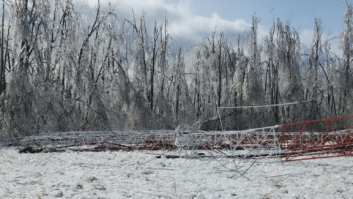
Fig. 1: There’s a reason they call it an ‘ice bridge.’
Winter and spring have been rough seasons all over the country. Director of Engineering for Montpelier Broadcasting Jon Hosford just got back from a trouble call on top of Ricker Mountain, home of the WNCS(FM) transmitter plant.
The original trouble call was about the failure of his main STL. When Jon and Chad Brosseau finally got to the site, they were greeted with the scene in Fig. 1. That’s Chad in the picture, at the base of the tower, providing visual scale.
One heck of a piece of ice obviously had fallen off the tower (and the top is only about 80 feet high). Ah, winters in New England.
But the picture doesn’t describe the whole story. As bad as this looks, none of the lines was damaged. The ice bridge did its job.
If your area is prone to ice, don’t let management talk you out of an ice bridge.

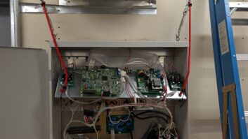
Fig. 2: A labor of love: Buc’s home brew processor undergoes final inspection. The rest of the story, and another lesson to be learned, were inside the building. When the ice hit it yanked the 1-5/8 transmitter feed line all the way back to the transmitter, a Harris HT3.5. Sitting loose on top of the transmitter was a fairly heavy Sloane filter for the STL receiver. It promptly fell off, yanking the cables right out of three of the four connectors. Jon writes, “It’s hard for an STL to work without an antenna connected to it.”
He replaced the jumpers and the main STL was back in service. Problem solved.
The moral: Never assume your transmitter can’t move enough to knock something off its top. I’m sure engineers from stations in earthquake zones understand that; but on a mountain in Vermont?
The Sloane filter now is securely tied so that it won’t fall again. Yes, in a perfect world there would be nothing on top of a transmitter; but Jon doesn’t live in that world.
* * *

Fig. 3: Once upon a time, every engineer had time to build projects like this. While we’re in Vermont, here’s a tip from Hall Radio’s Dennis Snyder for engineers who still enjoy troubleshooting down to the component level.
Rather than just relying on the trusty “solder sucker” to clear component holes, Dennis says, stop by your local welding dealer and purchase an oxygen/acetylene tip cleaner. They are under $10; Dennis suggests you select the one with a longer cleaning wire.
The tip cleaners are made of stainless steel, therefore the melted solder will not adhere to the wire. In a tight location, this wire can reach the solder-filled hole and clean it out much easier than a solder sucker. Be sure to select a size smaller than the component leads you are cleaning.
The tip cleaner wire can be aligned directly on the center of the lead hole on the component side of the board. Apply a little pressure. With the iron on the opposite side of the board, as soon as the solder melts the wire should pass through the hole.
There’s another benefit: The tip cleaner wires have serrated edges. Therefore the tool can be used as a miniature rasp file to clear the remaining solder by enlarging the component hole. If the board uses plated-through holes, Dennis urges caution that you don’t remove the plating as you clear the hole.
Thanks, Dennis, for a great idea — inexpensive, too.
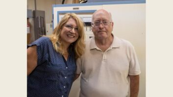
Dennis Snyder is director of engineering for Hall Radio’s Burlington, Vt., cluster.
* * *
Here’s a little nostalgia, especially for the more senior engineers reading this column.
There was a time — before an engineer might have to take care of 10 or more stations in multiple markets — when you had time to experiment and build things.
Fig. 2 shows a beauty shot of a “vanilla” broadband audio limiter, made using Spectra Sonics audio modules and built by Buc Fitch.

Fig. 4: An ingenious way to keep your coffee warm. Buc is constructing these for stations in Honduras. In Fig. 3, you can see the hand-wired PCB power supply and meter amp. The latter uses a variation of the circuit discussed in his 2008 op amp article in Radio World Engineering Extra. The meter is at rest at 0 dB and deflects downward to show compression.
Ben the cat is Buc’s QC inspector; Ben was intrigued by the bands on the 2 watt 680 ohm load resistor on the back terminal strip during checkout.
By the way, Buc needs a schematic for the Spectra Sonic modules. If you have one, please let him know. Contact Charles “Buc” Fitch, P.E., at [email protected].
* * *
Talking about building things: Robert Richer, an engineer in Connecticut, sent in Fig. 4.
Hey, an engineer’s got to keep his coffee warm. This coffee cup warmer is energy efficient.
Send me pix of your own good ideas, station catastrophes or visual humor. I’m at [email protected].
John Bisset marked his 40th year in broadcasting recently. He is international sales manager for Europe and Southern Africa for Nautel and a past recipient of the SBE’s Educator of the Year Award. Reach him at [email protected]. Faxed submissions can be sent to (603) 472-4944.
Submissions for this column are encouraged and qualify for SBE recertification credit.


