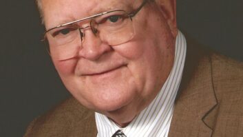
Ronald James Rockwell, right, and Clyde Haehnle. The occasion was Rockwell’s 1965 retirement party. You don’t hear a lot about homebrewing radio gear these days; it’s just too easy to call a salesperson or go online and find what you need.
I doubt anyone would consider homebrewing a broadcast transmitter, not even a pre-sunrise AM rig that could output only a few watts. If someone told you that he’d decided to roll his own 50 kW rig, you’d probably laugh him all the way to the door.
However, there was someone who once did just that. Not only did it work, it was touted as delivering the “highest fidelity radio transmission in the nation.”
That someone was Ronald James Rockwell — better known as R.J. Rockwell — who reigned for many years as the vice president of engineering at Crosley Broadcasting.
So why did Rockwell decide to take it upon himself to create a 50 kW broadcast transmitter?
No one knows for certain; however, it would not have been due to lack of funding. The Crosley Company (Avco by then) certainly had plenty when it was time to think about replacing the aging Western Electric 50 kW transmitter that had been in operation since the late 1920s at WLW. (Even in the station’s “superpower” phase, 1934–1939, when the WE rig wasn’t connected to an antenna, it served as the driver for the big RCA 500 kW “amp.”)
According to Clyde Haehnle, who had been with the station since the early 1940s, and was a senior engineer at WLW then, it was believed that Rockwell wasn’t happy with what he found in the way of commercial transmitters.
The one-of-a-kind WLW Cathanode transmitter.
(Click to Enlarge)
“He wanted a transmitter with very low distortion,” said Haehnle. “None of the available models came close to meeting his requirements, so he set about to design and construct something that could. One of the things he wanted to accomplish was to eliminate the big plate modulation transformer, as he saw this as a source of distortion.”

Haehnle remembers that Rockwell carried such a high profile within the WLW organization, there were no issues in convincing upper management to let him take on the job of designing and constructing a radically new type of 50 kW transmitter.
“He had an absolute carte blanche to build the transmitter. Rockwell never had any trouble on selling projects to management.”
WHERE DID IT START?
After more than half a century, it’s not certain exactly how long Rockwell took to arrive at a totally new approach to amplitude modulation. The idea may have its roots in the ’30s when WLW was still running half a megawatt.
Examination of a Rockwell patent application from mid-July of 1939 — little more than four months after a court decision throttled the station back to a mere 50 kW — provides evidence that he was thinking about new modulation methods.
The patent (granted in 1941) described a method for simplifying a transmitter’s modulation system, and began with description of the Class B (Barton) modulator hardware needed for the 500 kW transmitter — eight 100 kW triodes.1

The cover sheet of the 1956 application to the FCC for type acceptance of the Cathanode rig. Rockwell devised a way to reduce the tube count to four by shifting the alternate (“bottom half”) cycles, which would normally be handled by the lower half of a Class B circuit, back to the same tube that amplified the “top half.” While this sounds a bit like single-ended Class A operation (and Rockwell’s circuit used only one high-power triode), it wasn’t. He employed a couple of small triodes and two rectifiers as a means of “switching” alternate half cycles to the big tube (which was biased for Class B). It’s not known if the circuit was ever tried on the air, but it’s doubtful, as by that time, WLW was not making much use of the 500 kW machine due to politics and the FCC.
A 1946 Rockwell patent application describes a somewhat more advanced scheme for attaining Class B modulation, with elimination of the conventional modulation transformer as its goal. Rockwell claimed his new circuit provided 20 Hz to 50 kHz bandpass with less than 1 percent distortion, and very low noise figure. The circuitry in this patent begins to bear some resemblance to the finalized Cathanode circuit disclosed some 10 years later. Curiously, while many patents are written in such a way as to conceal critical details of an invention, Rockwell provided a “parts list” with tube types and resistor and capacitor values, almost encouraging others to build it.
In 1949, Rockwell applied for another patent that has additional bearing on the Cathanode circuit. Its title was “Push-Pull Wide Band Amplifier,” and Rockwell cited his earlier “Modulation System” patent as the basis for the developmental work leading up to this invention. Again, a complete parts list was included.
Rockwell followed this with another patent application in July 1953 for a “High Fidelity Amplifier.” In its preamble, he cites developmental features set forth in earlier patents leading to this application, which describes a “double-ended high fidelity transformerless amplifier now known as theCathanode amplifier” [Rockwell’s emphasis here and below].
The circuit in this patent application (it was granted Sept. 18, 1956) is virtually the same as the Cathanode circuit used in his broadcast transmitter. Rockwell, in the application, noted: “It is a still further object of this invention to provide a very high fidelity amplifier in a relatively small number of stages, which is especially suitable for use as a Class B modulator.”
FROM THEORY INTO PRACTICE
While the 1953 patent application indicates Rockwell was on the road to a new form of modulation, there are no surviving records indicating when he presented the idea to WLW’s corporate chieftains, or when he ordered parts for the new rig.
Among the documents that do survive is an engineering report prepared for FCC type acceptance of the transmitter, and which completely describes the new machine. The report logically would have been prepared after the project was successfully completed — it’s dated Sept. 6, 1956. Curiously, Rockwell didn’t get around to disclosing to the broadcast engineering world the workings of his radically different transmitter for more than a decade, publishing a paper in the IEEE’s January 1967 edition of “Transactions on Broadcasting.”
In the IEEE document, Rockwell describes a “scaling up” exercise as part of the path to the final transmitter design. This was obviously done sometime prior to construction of the rig.
“In order to facilitate investigation of the Cathanode circuit prior to construction [of the 50 kW transmitter], a low-power modulator stage was set up using Western Electric 300B tubes since they were close in characteristics to the Federal Type 6921 tubes to be used in the transmitter.”2
Haehnle recalled the actual design and testing of the new rig.
A circuit drawing from one of Rockwell’s many patents. The striking symmetry portrayed in this diagram is evident in most of Rockwell schematics. It typifies the inventor’s love for symmetry in everything he constructed.
(Click to Enlarge)
“I guess that it took about a year from the time the project started until the transmitter was on the air,” he said. “Once it was ready, we did a hell of a lot of testing before putting it on the air. We tested it for months and were very confident when we did the switchover.”

None of the surviving station employees remembers the exact date when the Cathanode rig was placed in service, but Dick Perry, who captured many of the WLW goings-on in his 1971 book, “Not Just a Sound: the Story of WLW,” pegged it sometime in January of 1959. Perry noted that the new transmitter was part of a $300,000 program to rebuild the station’s transmitting facility, stating:
“With these engineering changes the station management began calling WLW ‘The Nation’s Highest Fidelity Station.’ The WLW transmission was tested by the McIntosh Laboratory, Binghamton, New York. According to the report by Frank McIntosh, president, the WLW signal ranged from seventeen to 21,500 cycles per second — more than ten octaves — with a distortion of 0.3 percent. Mr. McIntosh stated that: ‘it should be recognized that while FM is capable of this same order of fidelity, many stations have not achieved it because of limitations in microphones, preamplifiers, circuits, and program sources.’”3
The 1959 startup date is confirmed in a Billboard magazine article that pegs it precisely as Jan. 19.4
A NEW FORM OF MODULATION
The concept of a “plate-modulated” transmitter constructed without a modulation transformer takes a little getting used to, as what’s going on in the circuit is not really that obvious on first reading. However, Rockwell’s development of unconventional circuitry was nothing unusual.
“Rockwell had a brain that wouldn’t stop,” Haehnle recalled. “He could out-think what a vacuum tube could do. He was brilliant. He could do things with circuits that you wouldn’t believe. He was a real bulldog — he just wouldn’t give up.”
Rockwell summed up the transmitter’s modulation system:
“This modulation system … involves a process in which audio voltage is obtained at any instant from both the anode and the cathode of a modulator tube. This voltage is either added to, or subtracted from, the split high voltage rectifier, and the resultant is applied to the anode and cathode of the final RF Class C amplifier as modulated DC — with no modulation or coupling transformer being involved.” 5
Not only did Rockwell successfully eliminate the modulation transformer, he made sure that the audio had a very clean path.
“Direct coupling has been utilized between the [input audio amplifier tube] and the [second audio amplifier], and between the [third and fourth audio amplifiers], thus leaving only two coupling condensers in the entire five stage audio system, thereby improving low frequency response and greatly simplifying low frequency feed-back circuitry.”6
The actual modulator stage consisted of two previously mentioned water-cooled Federal F-9028 triodes with 13 kV on their plates. These were biased “practically to plate current cut-off,” allowing the stage to operate in Class B mode. In a general description of the modulation scheme, Rockwell stated that each tube functioned independently in developing a 5 kV peak potential at its anode and at its cathode, with the two excursions amounting to 10 kV. This potential was applied to the plate and cathode of the Class C RF finals via two 5 kV rectifiers. These rectifiers were in a series-adding configuration and thus supplied 10 kV to the RF amplifiers.
Rockwell provided a precise description of the modulation process:
“One modulator tube adds its 10,000 volt peak output to the 10,000 volt Class C rectifier, thus providing 20,000 volt positive peak modulated DC as cathanode modulation … to the 50 kW RF amplifier; the other modulator tube subtracts its 10,000 volt peak output from the 10,000 volt Class C rectifier, thereby providing negative peak modulation voltage to the final amplifier.”7
Rockwell added that his circuit also reduced the possibility of “flashover” to ground in the RF output stage, as voltages were only half of what would be needed for modulation in a conventional circuit with the RF amplifier’s cathode at ground potential.
WHAT’S A CATHANODE?
Rockwell’s Cathanode terminology for describing his new type of modulation is indeed descriptive, but the term did not originate with him. “Cathanode” appears in at least one Bell Labs patent from the 1940s, and seems to have its roots in a 1932 patent application made by Raytheon’s James D. LeVan. However, in both patents, “cathanode” is used to describe an element in a cold-cathode “discharge” tube.
TRANSMITTER CONSTRUCTION
According to Haehnle, and another former WLW engineer, Charlie Stinger, the new transmitter was almost completely fabricated in house. Even the sheet metal for the transmitter cubicles was formed and painted by WLW personnel, along with the winding of power supply transformers.
“Mr. Rockwell obtained some power line transformers from Cincinnati Gas and Electric,” Stinger recalled. “We took these apart and completely rewound them to his specifications. One of the things that he was particular about was the wire — it had to be square, not round. I believe that it took a while to find that, but he did, and we rebuilt the transformers to his specifications.” Stinger suspects Rockwell specified square wire so that it could be wound tighter and had less chance of moving in the magnetic fields generated in the transformers. Haehnle suggested it was used to allow more copper conductor to be placed in a given space.
UNUSUAL POWER SUPPLY
Even the rig’s power supply was unconventional. Mercury vapor rectifiers were the norm then, but Rockwell insisted on using Cooper Hewett (mercury arc) rectifiers, a technology that hadn’t been used in transmitters since the 1920s. It’s not sure why he took this approach, but it may have been an attempt to save money on the heavily insulated filament transformers that would be needed for a conventional three-phase mercury vapor power supply. Alternatively, he might have wanted to use tubes without filaments to improve reliability.
Haehnle recalled the English-made mercury arc rectifiers were very reliable. (They carried a maximum rating of 270 kW at 15 kV.)
“I don’t remember that we ever had a problem with them,” said Haehnle. “In fact, we had less trouble with arc-backs with them than we did with the conventional mercury vapor tubes used in the big 500 kW transmitter.”
NOT QUITE PERFECT
Despite Rockwell’s painstaking efforts to develop a “perfect” modulation scheme, some problems did arise. However, these were not directly related to the audio performance.

The front panel of R.J. Rockwell’s “home-brew” ham radio transmitter. Notice the symmetrical placement of its meters, dials and knobs. The unit is on display at the Gray History of Wireless Museum in Bethany, Ohio.
(Click to Enlarge)
As recalled by Haehnle, one issue involved some “interferences” with patents held by audio legend Frank McIntosh. Haehnle stated that an amicable settlement between McIntosh and Rockwell was reached fairly quickly, with McIntosh journeying to Ohio to inspect the new transmitter and measure its performance.
The Cathanode transmitter also incurred an FCC citation during an inspection by John Reiser, who worked out of the commission’s Detroit office then.
“I issued a notice of violation because the transmitter’s antenna current meter didn’t conform to current FCC standards,” Reiser said. “It didn’t have the required number of scale divisions.”
Reiser recalled some other problems that could have brought an additional citation.
“There were parts on the inside supported by string or cords. They weren’t really permanently mounted, just suspended in free space. This sort of surprised me. I could have cited them for violation of good engineering practices.”
Perhaps the biggest problem stemmed from Rockwell’s 1965 retirement. The transmitter’s design was so unusual, it wasn’t that well understood by those left to maintain it. Stinger remembers that the rig required quite a bit of attention to keep it in proper operation, and Haehnle observed that it was designed for fidelity, rather than efficiency, with a resulting large power bill.
Within a few years of Rockwell’s departure, the Cathanode rig was gutted and rebuilt with conventional high-level Class B (Barton) plate modulation. It backed up the venerable 1920s Western Electric rig until 1975, when a Continental 317C1 became the station’s main transmitter. The “converted” Cathanode transmitter is still a part of the WLW transmitter facility.
A QUESTION OF BALANCE
Those that knew him say that Rockwell loved symmetry — maybe was even slightly obsessed by it. His circuit drawings reflect this, as components appear to be in perfect balance. Rockwell’s homebrew ham radio transmitter is also a good indicator of his quest for a balanced and symmetrical world. The left-side front panel meters, knobs and switches perfectly complement those on the right side. This quest for symmetry may explain Rockwell’s development of the Cathanode modulation scheme, which exhibits a high degree of balance and symmetry.
The author expresses appreciation to the individuals who assisted in preparation of this story including Clyde Haehnle and Charlie Stinger, former WLW employees who worked under the direction of R.J. Rockwell; John Reiser; and Jay Adrick of Harris Corp.
James O’Neal is technology editor of RW sister publication TV Technology.
REFERENCES
1 U.S. Patent 2,233,961 — “Amplifying System and Process” granted to James Rockwell on March 4, 1941 and assigned to The Crosley Corp.
2 Rockwell, R.J., “Cathanode Modulation System.” IEEE Transactions on Broadcasting, Jan. 1967, p. 22.
3 Perry, Dick; “Not Just a Sound: the Story of WLW,” Prentice-Hall, Inc., 1971 p. 79, 80.
4 “Crosley Debs Hi-Fi System,” The Billboard, Jan. 24, 1959, p. 4.
5 Rockwell, R.J.; Alberts, William S.; Haehnle, Clyde G., “Engineering Report: Application for Type Acceptance Rockwell Cathanode Transmitter Type EDS-530,” Sept. 6, 1956, p. 3.
6 Ibid; p. 6.
7 Ibid; p. 7.