Solid-State or Tube-Type? Some Considerations When Buying a New Transmitter
Not so many years ago, a decision to buy a new transmitter meant picking the brand with which you were most comfortable, negotiating the deal and waiting for delivery.
In FM transmitters, most lower-power models used a 4CX1000, 1500 or 5000 tube. A 20 kW unit meant a 4CX15000, and the really heavy iron used 4CX25000 or 4CX30000s.
Transmitters also were sold with triode power tubes, such as in the 3CX3000.
But whichever flavor you preferred, the order of the day where the power amplifier was concerned was tube, plain and simple.
Considerations
Since the 1980s, buyers have been faced with a choice: stay with the tried-and-true tube-type transmitter or switch to a solid-state variety.
At first, the choice may seem to be a no-brainer. Solid-state devices have come far since the early germanium days, when any room temperature above meat-locker range immediately destroyed the transistor. Modern MOSFETs don’t exactly thrive on high temperatures, but neither do they self-destruct under any reasonably normal conditions.
Add to that the efficiency factor and graceful failure modes of modern solid-state transmitters, and it would seem at first glance that a compelling argument could be made for forgetting tube-type transmitters altogether in favor of solid-state.
That argument would overlook several points that favor tubes over solid-state transmitters. In fact, tube transmitters not only survive in today’s broadcast environment, but quite a few are sold.
Why is this? What factors should be considered when making the choice between tube or transistor?
Prior to listing the pros and cons of both types of transmitters, let us state a couple of points.
Most, if not all, new broadcast transmitters use solid-state IPA stages. So the arguments made here regarding the advantages of tube-type transmitters actually refer to transmitters that are hybrids – units that have solid-state intermediate power amplifier stages feeding tube PA stages.
Also, very-low-power transmitters (1 kW and under) also are almost exclusively solid-state these days, so they are not factored into this discussion.
That being said, let’s go to press!
Costs
Let’s start by considering capital vs. operating costs.
From an initial cost standpoint, tube transmitters win, hands down. My most recent price comparison, within the past year, shows a price differential of about 20 to 25 percent between the types, with solid-state being the more expensive.
This difference seems to remain fairly constant across the range of available power outputs, so in actual dollars, the gap widens as the power goes up.
If just the initial purchase price is considered, the compelling argument would seem to tip in favor of the tube-type transmitter.
Ahh, if life were only that simple. Operating expenses must be factored in to get a true picture of transmitter cost, even though the initial purchase price of the transmitter is a capital expense (depreciated over the life of the unit), while the operating cost is a monthly expense.
The power amplifier stages in both types of transmitters have similar efficiency ratings, both being in the range of 60 to 70 percent, plus or minus a few percentage points.
These numbers, however, do not really tell the complete story. In a solid-state transmitter, there is little power consumption outside the shelves of ganged amplifier modules. Transistors, being cold conduction devices (as opposed to tubes, which are thermal conduction devices), generate little heat, because they have no filament.
What little heat exists is generated from the friction of electrons flowing through the device, and that amount is carried off easily by a heat sink. Each module has a couple of muffin fans to carry the heat off the sinks and out of the module.
Of course, the power supply is not without conversion losses, but as a function of the overall power consumption, these are relatively minor concerns.
Not so with the tube-type rigs. Instead of using small muffin fans, there is a large, direct-drive blower motor, sometimes as large as one horsepower or more, drawing 10 amps of 208 three-phase power every time the filaments are powered up.
Also to be considered are the screen power supply, the bias supply and the filament power supply. All of these elements use power, and decrease the overall efficiency of the transmitter. This takes the power factor of a tube-type transmitter down below a typical 50 percent, while the solid-state model chugs along at nearly the same efficiency as the combined output devices when considered by themselves.
So even though it appears that a tube transmitter is cheaper, in the long run you will pay the piper in the form of higher operating costs.
In my experience, at somewhere around three or four years, the extra power company charges will offset the lower initial purchase price of a tube-type transmitter.
IRR
If the only factors to be considered are initial cost and operating cost, a graph can be developed using your company’s Internal Rate of Return – just another way of saying how much your company figures it should earn on money it controls.
Chart the initial cost difference between the transmitters, the value of that money over time and how long the transmitter will have to last. From those numbers, you can calculate a total operational savings, and compare the types fairly.
Ahh, again, if life were only that simple.
Operational reliability must also be considered. In this area, solid-state transmitters have an advantage, but not an overwhelming one.
Because even modern solid-state devices are limited in power-handling capabilities – 500 watts being about the limit for a single device – manufacturers use internal combining networks to gang MOSFETs to achieve the desired output power.
This arrangement, while somewhat inefficient and expensive, has a nifty advantage. When two or more devices are paralleled into a combining network, there are always some losses, due to variations in circuit tuning and device conduction characteristics.
To keep these losses from reflecting back into the devices themselves, burning them up in the process, the combiner has a main output and a reject load output. The radiated RF goes to the output and the losses are absorbed as heat in the reject load.
Here is where the nifty part comes in. If one of the radiating transistors burns up, the other one continues to make power. No catastrophic failure, just a reduction in output power.
(Actually, since the circuit is now completely unbalanced, the reduction is quite substantial: a full 75 percent from normal. This is because the first transistor blows half of the power it is making into the reject load. Fifty percent of the original power went away when the first device burned up, and now, 50 percent of the remaining 50 percent is absorbed as heat in the reject load.)
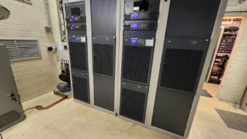
However, solid-state transmitters are made up of several “shelves” of combined circuits, sometimes 20 or more. As individual transistors fail, the power drops in small increments.
This is known as a “graceful failure” mode. No crash and burn, just a stairstepping down of output power as devices fail. It takes a horrible occurrence (unfortunately, not unknown in our business) to take out 10 or 20 transistors, so a total cessation of RF is unlikely due to a failure of output transistors.
There are, of course, mission-critical components in a solid-state transmitter, the failure of which can result in dead air. They include main power feeds and circuit breakers, VSWR failsafe circuits and power supply components.
As rugged as modern solid-state devices are, they are still more vulnerable to lightning strikes compared to a ceramic-bodied power amplifier tube.
Things can and will cause solid-state transmitters to give it up, but how do they stack up against failure modes in tube transmitters?
All or nothing
Tubes do wear out, due to the slow but steady erosion of the electron-rich material boiling off the incandescently heated filament, causing a gradual reduction in output power.
Beyond that, tube transmitters, although extremely rugged, are plagued by the “all-or-nothing” syndrome. Most tube failures are catastrophic. One minute the ol’ rig is humming along; the next, it’s belly up. The reason: there is only one radiating device in the transmitter. If it fails, that’s it; show’s over.
Moreover, there are multiple failure points that can cause the same results: Open or shorted screen power supplies. Open filament transformers or return circuits. Shorted plate insulators, sometimes called blockers.
An absolute army of parts can occasion the dreaded “off-air” call from the remote control.
Still, modern tube transmitters are reliable to an amazing degree, and as stated above, extremely rugged, being relatively impervious to mistuning, near-lightning hits and other bogies.
Many, perhaps most, tube transmitters literally run for years with not a minute of downtime due to unplanned total failures. However, that record must be tempered with the realization that those failures, rare though they are, are still by definition, “total.”
So, tube or not tube? That may be the question, but the answer is not definitive. It really does depend on many factors.
Does your station have a healthy standby? Do you have enough capital to invest in a pricier rig to begin with? How long will you or your company own the station? How much does power cost in your market?
These are all factors to weigh when making this decision. The competent engineer will give them careful consideration before making a recommendation he or she will have to defend every time the phone rings in the middle of the night.
RW welcomes other points of view