Two things have been overlooked with phasing amplitude modulation. One is the importance of pulse modulation; the other is that logic gates can be used for analog signal processing. Both of these things were new areas to explore, along with how far was it possible go with these ideas.
There are three types of pulse modulation that can be used to build other waveforms with. There are pulse width modulation (PWM), pulse phase modulation (PPM) and pulse location modulation (PLM). Whereas PPM can be used to generate the other two forms, PWM only has amplitude information and PLM only has phase information. So to be able to move from one form to the other depends on what is required: amplitude, frequency modulation or both.
By using PPM, we can do both phase and amplitude modulation, as demonstrated with this new phasing modulator amplifier design. This technique is able to work with both radio frequencies (RF) and with light at optical wavelengths.
Over the last three years during which I have been working on this phase modulation technique, it has been a test case to prove and evaluate the findings. Once this is done, the process is repeated again and again, making small improvements with each iteration.
Throughout this research process, it was not possible to go on the internet and see how this technology should work. By being first, there is no limitation on what can and cannot be done. The downside is that it takes a large amount of time to make small amounts of progress.
I also had ongoing support from Stephen Nitikman at our local college electronic labs, working through many different ideas throughout this process.
Once everything was working in class D, this amplifier was pushed into class E and I replaced the low-pass filter with a bandpass filter. The negative was poor modulation of 65.536 kHz; it was too low to be received on an AM broadcast radio.
The next step was to increase the frequency again to go above 150 kHz, to fall within the longwave band. I found that PWM was a limiting factor to modulating the carrier, so it was time to move away from using PWM and to try again with PPM. This is how the two unknown classes of switching amplification were found. At this stage, I needed to do more research into other forms of switching amplification and could not find any match to what I was working with.
After these experiments, I added in a field-programmable gate array (FPGA) into the circuit and used its PPM waveforms as a starting point. It was then possible to modify these pulses with logic gates to build a phasing modulator.
Looking at what was done with the Tayloe mixer and taking a new approach is where the Taylor modulator came from. It is far more than a simple switching RF mixer. The Taylor modulator takes the analog building blocks and converts their analog stages into logic equivalents.
This is an interesting area of discovery that falls between both analog and digital technologies, letting us take the best parts of both to work with. Once I worked out the required logic blocks and how they would go together to build the analog digital modulator (ADM), I soon found it was possible to use it with in-phase and quadrature (I & Q) inputs.
REQUIREMENTS
There is, in my view, a need for a transmitter that has lower total harmonic distortion (THD) and higher amplifier efficiency than any broadcast transmitter that is in production. What is the best way of going about designing such a device?
With AM, there are a number of stages that present problems in reaching these aims. The way to move forward is to look at other ways to generate the desired type of modulation to eliminate many of these shortcomings.
The power amplifier would need to operate in a switching configuration for the highest level of conversion efficiency from the DC input to the RF output stage. The only way this could be done would be by using some form of phasing modulator in combination with a switching amplification process.
Let’s take a look at a couple of current I and Q mixer designs.
Phasing Modulator Version 1
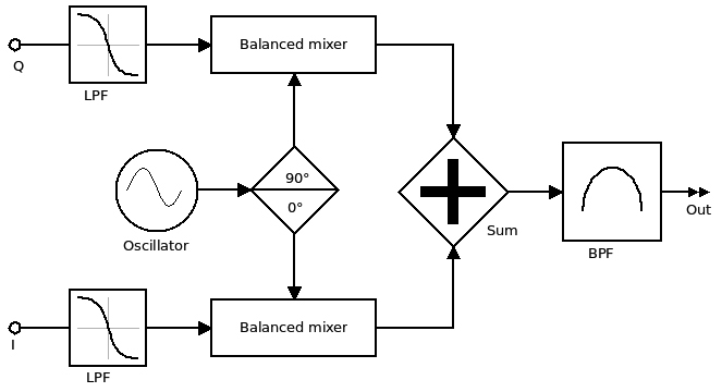
The most common type of phasing modulator is made up of two balanced mixers offset by a 90° phase shift network. The oscillator is fed into this phase-shift network and each of the two inputs are driven via low pass filters. The two outputs are then combined and fed through a bandpass filter, leaving only the desired frequency. See Fig. 1.
Tayloe Mixer Version 2
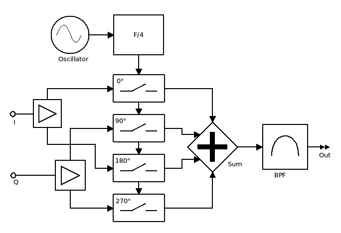
The other common type of phasing modulator is the Tayloe mixer, whereby the phase offset is done in logic by a divide-by-four, generating in this case four phase angles: 0°, 90°, 180° and 270°. The mixing is done with an analog switch, rebuilding the desired output frequency and as with the other type, this is then run through a bandpass filter. See Fig. 2.
BACKGROUND
The phasing modulator has been around since the 1940s. In its early form, it was used to generate SSB as a more efficient transmission format over AM that was widely used at that time. This is when we started working with In-phase and Quadrature inputs, to represent each part of the waveform as Phase and Amplitude.
While AM radio broadcasts have been around for more than 100 years now, the basic idea remains the same, with many improvements made over time. AM radio sound quality has also changed over time. The biggest impact came about with the invention of the super heterodyne receiver and its limited bandwidth, which is a design feature to increase selectivity and reduce adjacent-channel interference, and has therefore limited the audio frequency response to below 7 kHz. This is only one of the factors that have an impact. The others are the overprocessing of modulating audio and poor linearity of modulators and RF amplifiers stages.
Up until now, we have been generating various waveforms and measuring the effects of the pulse widths to work out the minimum required bandwidth. The process described herein works the opposite way and uses pulses to generate various waveforms. This technique is able to work both ways.
This type of quadrature amplification was invented in 2017. After experimenting with an optical road safety system called the Electronic Eye Project, it was soon discovered that the same process could be modified to work at radio frequencies. This form of switching amplification is made up of two parts, one being a phasing modulator using In-phase and Quadrature inputs, the other a switching output stage that acts as the amplifier. For this process to work, it must have a minimum of four pulses: two for the In-phase components positive- and negative-going, and the same for both Quadrature components.
Classes of Amplification
From the beginning of electronic amplification devices, there was a requirement to understand how the amplification process has been done. The way this was worked out in the analog classes was by using angles to specify the on time in degrees. So you had Class A that conducts for all 360° of the cycle, Class B that conducts for 180° x 2 of a cycle, and Class C that conducts for just a few degrees of the cycle and uses an L-C tuned circuit combination to restore the full cycle. With switching amplification, classification is based on the type of switching and the way the output filtering is being done.
Types of Pulse Modulation
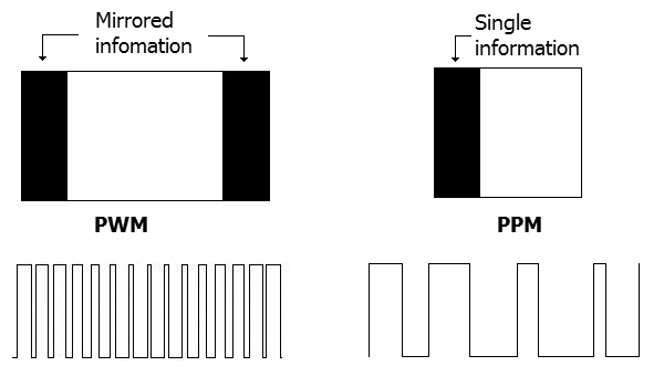
PWM has the same information on both sides of the pulse but is mirrored or 180° out of phase, and the phase information is canceled out, leaving just amplitude information. By converting PWM to PPM by removing one side, we keep all the encoded information as well as the all-important phase information. This is, in a way, like what you would get with amplitude modulation with the sidebands on each side of the carrier when all that is needed is just one of the side bands to convey the information.
PWM Amplification
Class D and I are switching amplifiers. Class D uses PWM. This process chops the sine wave into wide or narrow pulses. The widest point of the pulse is at the peak of the sine wave and the opposite at the minimum point. With Class I, there are two in-phase PWM carriers that are connected to a common clock, using a differential process where one input is offset to the other by 180°. This means the audio input needs to be phase-shifted by 0° and 180° to drive each PWM input.
Both classes of amplification, therefore, are linear. What goes in comes out with very good efficiency. These are known as switching classes, and all require filtering after their output stages to remove unwanted harmonics. In class D and I, a low-pass filter is used.
The efficiency of these classes comes from the output device being turned hard on and off, minimizing power being dissipated within the switching device.
Quadrature Amplification
Quadrature amplification starts out with two signals that have the same frequency and are offset by 90°, which is expanded out to four phase angles that have an offset of 90° (0°, 90°, 180° and 270°). Unlike Class D, quadrature amplification works at minimum of four times the highest frequency, where Class D works at a minimum of two times the highest frequency.
Another difference between the other switching classes is that quadrature amplification uses PPM and not PWM. The latter has no phase information and is therefore used to vary only the amplitude. However, if you remove one side, you end up with both the phase and amplitude components. In quadrature amplification, the amplitude part is not used.
Phase information is processed within logic gates and by adding I and Q pulses together, and with that, it is possible to rebuild any type of analog waveform. This is where Nyquist is very misleading, stating you only need two pulses to regenerate a sine wave. This is not true for phase integrity, where you need a minimum of four. This is the key difference between quadrature amplification and what happens in Class D and many other switching classes.
Class P and Q
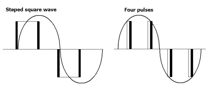
Class P and Q are unique due to the way that they are based on phasing principles, so you will have sine and cosine parts to the step waveform. These amplifiers employ four pulses as parts of the generated analog waveform: two positive-going and two negative-going. This approach is used in these new forms of amplification, moving on from the limitations of class D and the two-times-clock technique.
There are two forms of quadrature amplification, which I will call Class P and Class Q. In Class P (pulse), you have four PPM pulses that are offset by 90° from each other. In Class Q (quadrature), each side of the pulse has the in-phase and quadrature information.
In Class P, each pulse must have less than 25% on time, and you have a gating window that the pulse must fall within. The PPM, therefore, is between 0% and a maximum of 25%. It must be triggered to start at 0°, 90°, 180° and 270°. With PLM, the pulse just needs to be within the gating window. The output waveform, therefore, has 0° and 90° positive-going, and 180° and 270° are negative-going pulses. Possible uses for Class P would be in applications where you need an extra level of processing between input and output stages, whereas Class Q has the higher efficiency of the two.
With Class Q, the maximum on time is 50%, where you will end up moving into Class E (square wave). Therefore, when amplifying a modulated signal, you always will be less than the maximum of 50% on the positive- and negative-going cycles to provide room for modulation. Where there is a sharp cutoff between the linear and nonlinear zones, this starts to have an impact above 25% pulse average until you reach 30%, where it mostly becomes nonlinear. Another way to look at Class Q is that it provides the linearity of class A with the efficiency of Class E, making it ideal for many forms of analog and digital modulation systems.
With quadrature amplification, it can also be used for audio applications, but there is no real advantage over existing classes like D and I, so my focus has been on RF applications where I and Q inputs are used.
The phasing technique used is the same for both classes. The only difference is in pulse processing stage of the modulator. In Class P, you have four time slots for each of the angles, where one side of each pulse is modulated (PPM). The location within that time slot can also vary, using pulse position modulation. In Class Q, each side is modulated. The positive side has two parts of the information and the negative side has the other two. With Class Q, the 0° and 90° phases are set in the pulse processing stage, but are not so important in the pulse converter stage.
As with Class D and all the other switching classes, output filtering becomes very important to rebuild the analog waveform. Both Class P and Q use low-pass, bandpass or a combination of both.
The table shows amplifier grouping types.
A Class Q AM Broadcast Transmitter
By using one dual device and doubling the frequency, in logic I then did a divide by two, bringing the operating frequency back down to 660 kHz from 1.32 MHz. With this version, it modulated both digital and analog waveforms with very good linearity. For analog testing, I used AM Stereo (C-QUAM), and for digital, Digital Radio Mondiale (DRM) was used at 64QAM.
The current prototype has elements of all the other versions as well as new ideas for the first fully-working AM transmitter. Whereby in this configuration you are able to operate up to the maximum frequency of 10 MHz, this is well within the range of the AM broadcast band from 540 to 1700 kHz. All the testing was done over three frequencies, 660, 1110 and 1500 kHz, where there were gaps found between local radio stations. For the output power, I was getting a maximum of 200 watts at 100% modulation, using an LDMOS switching device.
Operating in I and Q Mode
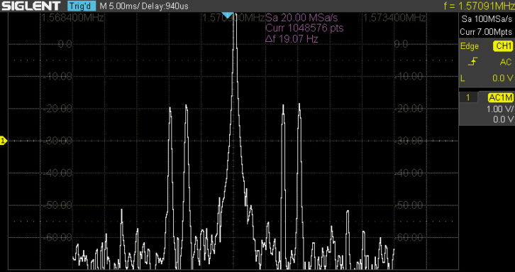
Operating in I and Q mode with DRM using an offset of 12 kHz, there is no issue generating any waveform type, regardless of the type of information been sent analog or digital. A waveform as complex as COFDM can easily be modulated. The only limitation is the linearity of the phase modulators used. This is why the THD is so important.


Unlike other types of analog RF amplifiers, this configuration uses very nonlinear amplification, just two states: on and off. So phase noise and phase distortion effects need to be minimized wherever possible. This is why so much negative feedback was used in various parts of this circuit.
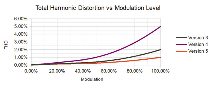
From Fig. 10, you can see the version using two phase modulators with better switching output devices made an improvement over Version 4 using the four-phase modulator design. This was due the switching power MOSFETs that had a higher amount of phase distortion.
In version 5, a newer design was used for the negative feedback path, using two PWM signals through a low-pass filter driving back into each of the inputs of the phase modulators. With quadrature amplification, it is an ultralinear process, where most of the distortion takes place in the phase modulator stages (converting the analog inputs to PPM or PWM). With ongoing improvements, I am sure it is possible to bring this level of distortion down, closer to 0.5% at 100% modulation.
NEXT VERSION
I now have my first working product based on the experimental work done with all the previous versions. The next version is a 100-watt model that operates in Class Q with a small number of improvements, such as using a new type of phase modulator design, providing a wider frequency range from LF all the way up to HF. It also has an in-built audio compander stage just before the preemphasis to provide improved signal-to-noise performance on the receive side. The plan is to go with this design for on-air testing here in Toronto this year.
The 1 kW model uses the NXP MRFX1K80H device. For higher efficiency, I am working with a switching DC power supply rail to operate in class G and Q using a combination of techniques from the older versions with flexibility from a common hardware layout. Quadrature amplification is a fully scalable process, making for much higher power levels above 1 kW possible with minimal design changes.
This transmitter design is lost on your average AM receiver. I am using a Denon TU-680NAB receiver connected to a Pioneer EX-9000 expander, and this is providing good off-air performance with this setup. With renewed interest in AM stereo, I hope manufacturers will soon get the message and start making receivers again — it is not that hard to do in a single DSP chip these days.
Grant Taylor started experimenting with a simple FM transmitter in high school. He spent the next few years experimenting with home-made television equipment within amateur radio. From there, he worked repairing and installing outside broadcast links in New Zealand, which led to working on local radio and television infrastructure projects. He experiments with new technologies that have applications in broadcasting.