Lee Granlund wrote in the Sept. 1 issue of Radio World on “Common Misconceptions About FM Antennas.”
In May of 1973, Bellevue Community College, Bellevue, Wash., expressed a desire to construct a 10-watt, low-power FM radio station for the benefit of its students and the surrounding community. The college applied for, and was granted, a license for educational station KBCS (BCS meaning Bellevue College Station) on 91.3 MHz. Hearing of the plan, I offered to donate my services.
The college’s budget for this project was low to nonexistent. It did have enough funds to purchase and construct a 100-foot tower and some other basic equipment, such as an audio mixing board, microphones, LP turntables and audio tape machines, but it did not have the money for the necessary RF equipment.
Peanut power
At the time I was employed as a studio engineer for KING-TV, Channel 5, Seattle. I happened to mention that I was looking for an FM 10-watt transmitter to Lee Mudgett, the KING-TV and KING-FM transmitter supervisor. He said the station might donate its old RCA vacuum tube FM exciter to the cause.
After hearing of the idea, Dorothy Bullitt, the owner of KING-FM, was enthusiastic and gave the green light for the donation transfer.
I took the exciter to my shop. After checking the condition of its vacuum tubes and installing one of the two 91.3 heated crystals from RCA, I connected the unit to a Bird Wattmeter, a low-pass RF filter and a dummy load.
After I tuned it to its new frequency, it demonstrated a solid 10 watts of RF output. The crystals were checked for frequency accuracy and both were well within FCC tolerances. Two crystals were ordered, one for the transmitter, a second one to be placed in the desk of the chairman of the college’s communications department as a backup in case the first one failed or disappeared.
During the week, I let the unit cook to check its stability. I even fed some 1940s network radio programs from my collection and other audio sources through it to check for audio quality.
It sounded as good as it did when it was on the air at KING-FM. Even though it was feeding a dummy load, it could still be heard for about 100 feet, well within the FCC 100 milliwatt limited radiational limits. The neighbors were amazed when they heard old-time radio shows on 91.3 FM.
The college recently had purchased two homes located adjacent to the campus; now the radio station was installed in the daylight basement of one of these houses. I donated an old vacuum tube Altec audio limiter to prevent over-modulation. Unlike today, in the startup days, the station was strictly monophonic.
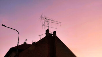
The antenna consisted of two horizontally polarized dipole units, spaced vertically on the side of the tower, near the top. The antennas were pretuned to 91.3 and the package came complete with wiring harness and connectors. They were mounted in such a way that the main RF lobes were pointing toward downtown Bellevue. The transmission line was 1 inch flexible foam Heliax.
After final tuning, the standing wave ratio was 1.1 to 1, demonstrating an efficient, acceptable antenna match.
The transmitter and tower were grounded properly by driving a 2-inch copper rod 10 feet into the ground. This was not only to provide protection against lightning strikes, static charges and shock protection, but also to provide a solid earth ground counterpoise for the entire RF system.
Booming in
While some people might say that this was FM so proper grounding of the RF system would not be necessary, I have come to the conclusion that it is very important.
A solid, low grounding impedance for the RF potential to reflect against is just as important as having the proper transmitter and antenna.
At that time, my son lived near Everett, a city located about 40 miles north of Seattle. KBCS(FM) came booming in at his home as well as when we drove around Everett listening to the station on my car radio. The station was heard easily in all parts of downtown Seattle, a distance of about 12 miles. The coverage was unbelievable, and with only 10 watts. It was amazing.
It was concluded that this signal efficiency was due to a number of factors: (1) employing the proper antenna and transmission line, (2) being located on the top of a hill, (3) maintaining a solid connection to the earth, and (4) good ground conductivity.
While all of this may not be solid engineering data, it still demonstrated to me the value of employing proper antenna installation and grounding techniques.
In my opinion, Mr. Granlund is absolutely correct in stating that commercial FM antennas are not all alike. I would go further: FM installations are not all alike. Pay close attention to grounding methods and how the RF energy is transferred from the transmitter to your listeners. This can make or break any FM operation.
Jerry D. Burling, CSTE, is a contract engineer in Long Beach, Calif.