It was late 1984, some 39 years ago this month, and I was new to the company where I still work today. Right out of the chute, the president of the company handed his new D of E an assignment: Fix our Detroit FM station.
We had in those days two “superpower” Class B FMs in our company, one in Buffalo and one in Detroit. Our Detroit station was 115 kW ERP at 300 feet above average terrain, impressive by any measure, at least on paper. The problem: The Detroit FM had severe multipath throughout the market and was unlistenable in many locations.
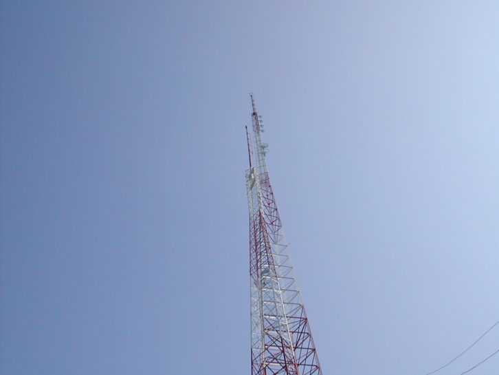
The site was right in the geographic center of the Detroit metropolitan area, near the intersection of I-96 and the Southfield Expressway. The station had an RCA 10-bay antenna, pole-mounted on a 360-foot free-standing tower.
The antenna looked fine and the transmitter was operating at full power. There was no indicated reflected power. What could the problem be?
Some sleuthing and scrutiny of the geography and topography of the Detroit area gave me some clues.
The downtown area, with its buildings some 600 feet tall, was about 10 miles to the east, and there were other high-rise buildings scattered around the area, some not far away. Could those buildings be producing strong reflections to cause the severe multipath that the station was experiencing?
At that point in my career, I didn’t have much experience with FM except at the operational level; I had been a TV guy until just months prior. I had done some FM allocations work in addition to building and maintaining a few FMs, but what I had not done was any kind of systems engineering. All my experience on the ground was building or maintaining what other people had designed, so I was out of my element with this project.
Still, I had it to do, and while not expressly stated, I figured that this was a test and that my job was on the line. I had to get it right.
And so I took a self-administered crash course in FM antennas, vertical plane patterns, multipath and FM propagation. I learned about vertical nulls, Brewster angle and how direct and reflected signals could constructively or destructively combine in a receive antenna. I also learned how subcarriers could sometimes produce multipath-like effects in an imperfect transmission system or where there were already signal issues.
At the end of that study and my analysis of the situation with our Detroit station, I concluded that we had too much antenna gain, too little signal in close-in areas below the main vertical lobe and reflections off the downtown and other high-rise structures that were destructively combining with the direct signal to produce the multipath.
Was I certain of all that? No. But it was my best, somewhat educated, guess.

[Sign Up for Radio World’s SmartBrief Newsletter]
Superpower FMs had been grandfathered, but if you made a change to the HAAT or ERP, the facility would have to come into compliance with the later rules. Clearly we needed more height, and to get that, we would have to become a compliant Class B station with maximum facilities of 50 kW and 150 meters (492 feet) AAT.
It was with great anxiety that I took that proposal to the president of our company, telling him that the way to fix his FM signal was to reduce power from 115 kW to 50 kW. How would he respond? Should I just go ahead and clean out my desk?
To my great surprise, he gave his full approval to the project.
It included a new 500-foot free-standing tower (not cheap!), a four-bay antenna, new rigid line and a new 27.5 kW transmitter. That tower height got us 142 meters AAT, not 150 meters, but 500 feet AGL was all I could get the FAA to approve.
I filed the CP application and got a quick grant.
The project was built in record time by today’s standards, just a few months. There was no ASR, NEPA, NPA and all that back then … we just pulled a building permit, drilled the piers into the ground and stacked the steel.
With the new tower up and the new transmitter building in place and fully equipped, with great trepidation I threw the switch to put the new facility on the air. Would this huge expenditure fix our problems, or did I just throw several hundred thousand dollars down those pier holes?
It didn’t take long to figure out that YES! IT WORKED! The new facility had none of the multipath issues that the old one did. Coverage in the city was solid, with just a few identifiable and very localized areas with any discernible multipath at all.
But what about distant coverage? The station manager and others drove the outlying areas and found that the coverage was equal to or better than what it had been with the higher ERP. I was greatly relieved, and it was with great pleasure and pride that I reported all this to the boss.
I learned a lot from that project, and the knowledge has served me well over the years. I’m very grateful to my boss for his faith in me when I didn’t have a lot of faith in myself, and I thank God it all worked out.
I mentioned that our company had two superpower Class B FM stations, with the other one being in Buffalo. That one was 110 kW ERP at 195 meters (640 feet) above average terrain. It used a 10-bay antenna on a 400-foot tower. Buffalo had a lot of tall buildings like Detroit. If a high-gain antenna creates multipath issues in urban areas, why didn’t it do the same thing in Buffalo?
The answer is really simple: location-location-location. The Buffalo site was some distance south of the city. That tight vertical pattern had little impact on the urbanized area some distance from the antenna. That station continues to perform well for us, as does our no-longer-superpower Detroit FM.
In the current edition of Radio World Engineering Extra, Dennis Sloatman deals with some of these issues and teaches us about all the variables that go into an FM transmission system. He shows us how to arrive at a transmitter power output (TPO) figure given all those variables.
We also hear from Dominic Giambo of Wheatstone about RIST, a new, open-source protocol for audio transmission over IP and in particular the public internet. This is exciting and may well represent the next big thing in audio transport.
Does anything use quartz crystals anymore? Modern transmitters and their exciters are often frequency agile and can go to any frequency in the band with a menu selection, so surely not; why would you need a crystal?
Not so fast! Even modern, frequency-agile transmitters, receivers and other equipment have a quartz crystal at their heart, often a highly accurate, highly stable reference oscillator running at some low frequency. It’s true that it’s rare to find a crystal cut for the carrier frequency in a modern transmitter, but there’s some quartz in there somewhere.
In this issue, Buc Fitch takes a look at quartz crystals, including their history and how they are made and work. I think you’ll enjoy it.
I hope you’ll learn (or relearn) something from this group of really smart writers. I know I did.


