If you were to name a piece of broadcast equipment that is neglected, forgotten or taken for granted, the transmitter remote control would probably be high on the list. Nevertheless, remote controls have their own history, technological breakthroughs, pioneers and industry leaders.
From the earliest days of broadcasting, many stations had a remote transmitter site, and FCC regulations of the day stipulated that an engineer with a First Class license be on duty at the transmitter during hours of operation. Their duties were to keep the transmitter log, taking required meter readings every 30 minutes, as well as maintaining the transmitter parameters within FCC regulations. That meant keeping power output within in a plus 5 and minus 10% window, carrier frequency +/- 20 cycles, and modulation between 85 and 100%. These are things we take for granted today, but they required continuous scrutiny in the early days of broadcasting.
Those early transmitters were prone to frequent breakdowns. Electronic components of the day were not that reliable, particularly when high voltage and RF were involved. An engineer had to be on site to make timely repairs.
With advances in technology, transmitters became more reliable. The FCC regulations remained in place, however, and the transmitter engineer’s unofficial duties often were extended to include bench repairs and maintenance of equipment, rewinding carts and dubbing agency spots.
FCC ACTION
Gradually, the driving forces for remote control of broadcast transmitters mounted, and change was in the air. But it didn’t happen overnight.
Harold Hallikainen, engineer for manufacturer QSC LLC, said the FCC’s rollout of remote control authorization spread slowly across the broadcast spectrum.
“In 1950, the FCC proposed authorizing remote control of Class D NCE FM stations, which had a power output of 10 watts or less. The foundations of subsequent rules can be seen in this first proposal,” he said. “Control circuit faults could not activate the transmitter, and any faults causing loss of on/off control would shut down the transmitter. No telemetry was specified. Since all comments were in favor, the rules were adopted.
“In 1952, the FCC discussed the possibility of remote control of nondirectional AM stations and FM stations, both at or below 10 kW,” he continued. “The complicating factor of emergency frequency changes to comply with Conelrad requirements was also debated.”
In 1953, this authorization was granted. “Following a prolonged comment period, the commission authorized remote control of high-power and directional radio station in 1957. Television had to wait even longer. UHF stations were authorized in 1963, VHF in 1971.”
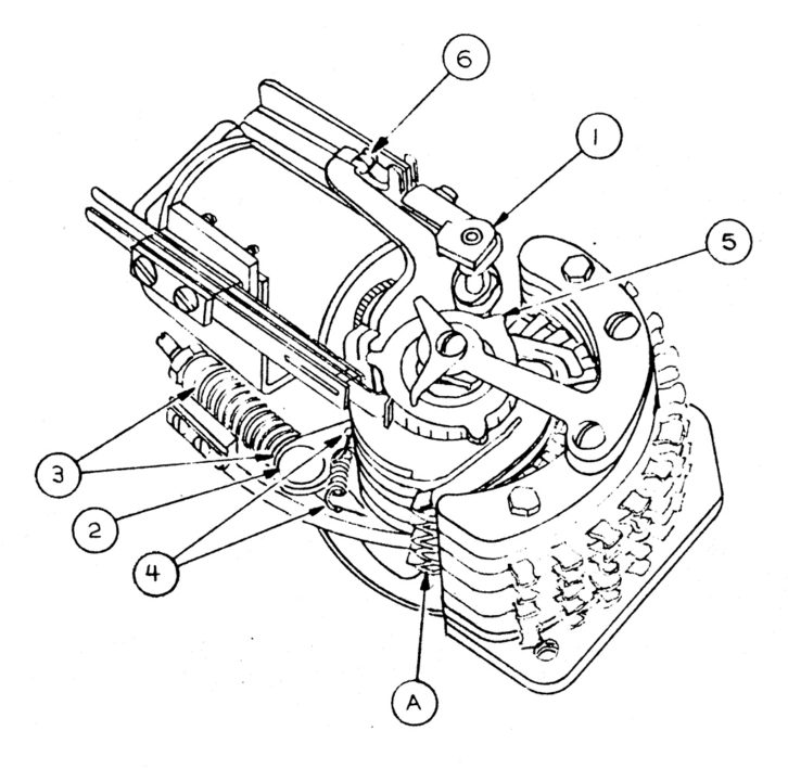
Radio broadcasting has long borrowed hardware and technology from the phone company. When engineers began to envision how a transmitter remote control would work, stepping relays were the logical choice. As the foundation of the rotary-dial telephone system, a stepping relay was basically a pulse-driven, multiple pole 1 x 10 switching matrix.
As manufacturers designed the first remote controls in the mid-1950s, basic elements began to emerge: a studio and transmitter unit, each with a four-pole stepping relay. One pole was for metering +, one for metering –, a third for raise functions and the fourth for lower functions.
Connection between the studio and transmitter units was by two phone lines, each with DC continuity. One was for metering, the other control. Both wires in the control pair worked against ground in a “simplex” arrangement, providing two independent control circuits. A DC voltage generated at the studio usually held in a relay at the transmitter side that controlled plate on/off, fulfilling the FCC requirement for fail safe.
All these systems had calibration pots on the transmitter side for each channel. When the engineer made the FCC-required weekly calibration of the remote control, he would call the studio and the operator would give the local meter readings. The engineer would adjust the calibration pots so the remote meters agreed with the transmitter readings. There was also a single calibration control on the remote unit, which was used to compensate for changes in loop resistance of the phone line, which varied as a function of temperature and humidity.
AUDIO TONES
One of the pioneers in remote control systems was the Rust Industrial Co. Inc. of Manchester, N.H. Founded in 1954 by W.F. Rust Jr., it also introduced a strip chart recorder for transmitter logging in 1958 and its advanced AUTOLOG product line in 1964. The company moved to Cambridge, Mass., and later Everett, Mass.; it appears to have gone out of business in 1974.
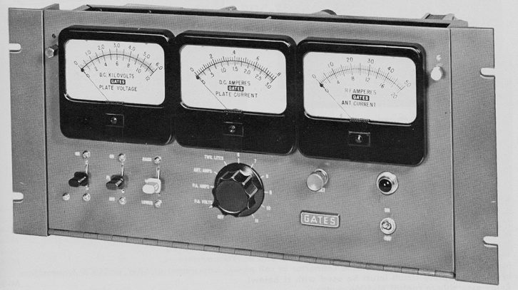
Gates also got in the game early with its popular RDC-10AC, as well as the long-forgotten RCM-20, which worked with audio tones rather than DC voltages, an innovative approach in 1955.
A 10-channel remote control was adequate to control two transmitters, but when large directional arrays were involved, or later, television transmitters, something more robust was called for. Gates introduced the RDC-200, which added three more stepping relays to provide 39 channels, and used a rotary telephone dial to access them. Other manufacturers developed similar offerings.
With some refinements to the metering and control circuits, this stepping relay infrastructure would be integral to most remote control systems for the next 20 years. These relays were not without their issues, however. The combination of rapidly turning the selector switch and a high-capacity phone line could cause the studio and transmitter steppers to get out of sync, resulting in erroneous readings. Stepping relays also required regular maintenance for reliable operation. That included lubricating wiper contacts and moving parts.
Moseley Associates was one of the first companies to embrace digital techniques in the design of remote controls. Its PBR-15 and -30, introduced in 1970, eliminated the stepping relay from the studio end. In place of the traditional 10-position rotary switch for channel selection was a ganged 16-position (on the PRB-15) push button switch. Binary numbers were generated by the push button assembly. They were then encoded to the stepper drive generator.
Control functions were handled by a 920 Hz audio signal that was briefly interrupted to send pulses to the stepping relay at the transmitter. Different tones were added to the 920 Hz for raise and lower. Metering signals were generated by applying the sample signal to a voltage controlled oscillator.
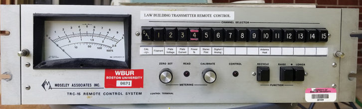
The successor to Moseley’s PBR-15 was the TRC-15, introduced in 1975. The PBR and TRC looked identical, but the TRC performed all control functions using frequency-shift keying technology. It also eliminated the troublesome stepping relay from the transmitter end. A control demodulator with SN74154 decoders and 7404 hex inverters connected to an individual relay for each of the 15 channels.
NEW OPTIONS
These Moseleys and other audio-based control systems had the advantage of needing only one phone line, resulting in an immediate reduction in operating costs. But there were far more important benefits to these new systems.
Once audible or subaudible tones were used for control and metering, several options became available for interconnecting the studio and transmitter units. In addition to traditional phone lines, there was the possibility of audible control over internal 110 kHz subcarrier generator and demodulator. Usually these signals rode from the studio to transmitter piggyback on the STL link. Subaudible metering returns in the 20–30 Hz range could be accomplished on FM stations via an SCA channel, which could also be used for background music or other programming. For AM operations, the subaudible metering signal was returned on the AM carrier. Modulation of the subaudible tones was set to around 5%.
Gradually, Moseley gave remote control circuitry a complete makeover, using TTL logic circuits, voltage controlled oscillators and other digital techniques. The one remaining weak link was the analog panel meter. Offset and gain drift were constant. Checking the zero set and CAL adjustments before taking a set of readings was mandatory. The analog meter precluded using the Moseley for any of the automated control and metering systems that were beginning to emerge. Also, the numerous scales on the meter could be confusing to non-technical operators.
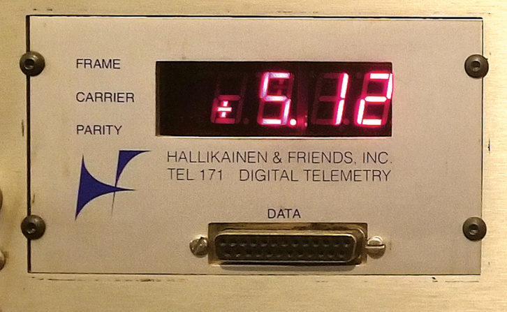
In 1977, the Moseley TRC-15 and PBR-30 remote controls finally got digital panel meters. But they didn’t come from Moseley, rather from a small startup company just down the road from the remote control manufacturer.
Harold Hallikainen’s company, Hallikainen & Friends, developed the TEL 171 to meet this need. The genesis of the TEL 171 was really an FCC inspection at a station where Hallikainen was chief engineer.
“The inspector dropped our Bauer 707 from 1 kW to 250 W, and asked the operator for the readings,” he said. “The operator read the wrong scale and gave the 1 kW readings, since everything doubled going from 250 W to 1 kW. This incident, the difficulty of calibration and misplaced decimal points were the things that inspired me to design the TEL 171.”
He adds, “It originally did not have a display at the transmitter site. KCBS said they’d buy one if we could make that happen. There was not enough power available to run an LED display off of the floating power supply. Around that time, the DF 411 chip was introduced. That made it easy to drive an LCD, so that was used for the transmitter display.” Hallikainen doesn’t recall exact numbers but estimates that a few thousand TEL 171s were sold.
The TEL 171 could be more than a digital display option. A DB-25 connector located below the display made available binary-coded channel select lines, raise-lower functions and the multiplexed BCD reading. Bill Bordeaux of Interstellar Engineering designed the ITO-177 (Intelligent Transmitter Operator). It plugged into a Commodore 64, and made the TRC-15A/TEL-171 controllable via BASIC programming.
SMOOTH UX
Other manufacturers were bringing digital to their remote controls, and had a different approach than Moseley. TFT introduced the model 7601 in 1982. It used FSK modems on each end. The Harris 9100 fully embraced the then-new FCC ATS rules enabling unattended operations. The emphasis was shifted from remote control of transmitters to facilities control. The logging software included trend analysis, enabling users to locate problems areas and anticipate failures.
Throughout the 1970s, Moseley had been the innovator in remote control technology and had the high end of the remote market to itself. When Gentner came on the scene, it changed the game with its VRC-1000.
Utilizing the DTMF tones from a phone, along with speech synthesis, Gentner eliminated the studio side of the remote control. All that was needed was to dial the site, enter the password and follow the menu options. It also meant the transmitter could be controlled from anywhere. The issue of how to accomplish the fail safe was resolved with a silence sensor. The concept of telephone access was developed by John Leonard of Moseley, who later sold the design to Gentner.
Microprocessors arrived in the early 1970s, powering the first generation of personal computers. Soon, they were being embedded in various electronic devices.
In 1980, Moseley introduced the MRC-1, the first microprocessor-based remote control, using an 8-bit Motorola 6802. It comprised one control terminal and up to nine remote terminals. Each remote site had 32 channels available. Alarm parameters could be created for each channel, and an automatic logging option enabled regular printout of transmitter logs. A CRT option duplicated all the functions of the MRC-1 control panel, and could simultaneously display data from all 32 channels at one site.
The coming of the internet was another game-changer for remote control technology. But as Peter Burk, president of Burk Technologies recalls, the rollout was rather protracted.
“In the early days of the internet, it could be difficult to get a connection to a remote transmitter site. Two solutions emerged, an Intraplex connection, or alternatives such as cellular modems, licensed and unlicensed wireless and satellite.”
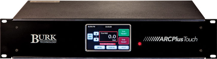
Burk’s first internet-based remote control was the ARC-16, which was able to control multiple transmitter sites. Even more impressively at the time, the system enabled site-to-site control.
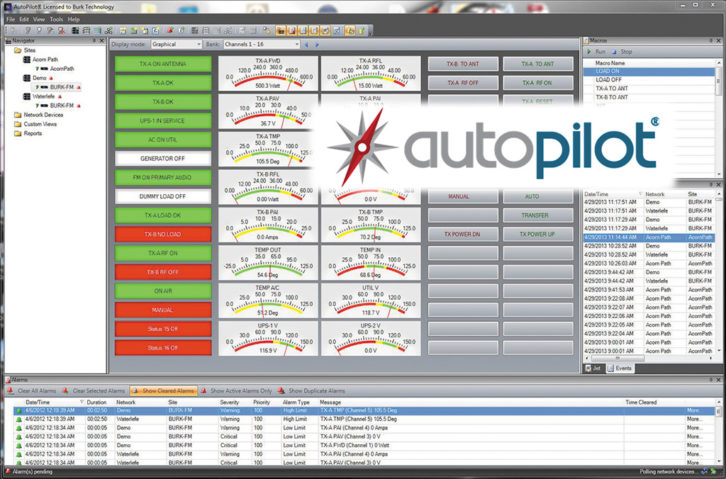
As with much of broadcast technology, the cutting edge for remote controls largely has shifted away from circuit cards in rack-mounted boxes to software running on PCs. Burk’s Auto Pilot enables multi-site, PC-based facilities management for Burk remote controls. The interface is customizable, and reports can be tailored. They can be printed automatically or emailed as a PDF to station personnel. AutoPilot includes network management functionality, bridging the gap between broadcast and IT by including SNMP and ping with traditional I/O.
The remote control segment has always been specialized. Ask an equipment dealer today and they’ll tell you about options from companies like Burk, Davicom, WorldCast Systems, Broadcast Tools, Broadcast Devices, Sine Systems and CircuitWerkes.
So what’s in the future for broadcast remote controls? Right now, the greatest force driving innovation seems to be artificial intelligence, although Peter Burk prefers the term machine learning.
“Our goal is to look at the wealth of data that is now available at a transmitter site and deliver predictive analytics. For example, assume your transmission line has developed a small leak, but the nitrogen tanks are keeping up with it. If you check the pressure, it will be OK. If the sensors are tracking the flow, however, they will see an increase. In this case, we would want the software to give you an alert to check the system before the nitrogen runs out and you have an emergency.”
Another trend is to understand that the remote control is now a part of the Internet of Things; equipment users and designers plan accordingly.
“One of the challenges is that IoT generates an enormous amount of information, and we need to find a better way to reduce this data down to actionable information,” he said.
Burk adds that human access to the IoT raises some interesting challenges. “Alexa and other smart speaker technologies bring with them the promise of the voice-activated Internet, as well as the challenge of building seamless interfaces. At the same time, accessing IoT via the screen of mobile devices is exploding, and the need for a smooth UX or user experience is paramount.”
Tom Vernon is a longtime contributor to Radio World. Comment on this or any story. Email [email protected] with “Letter to the Editor” in the subject field.