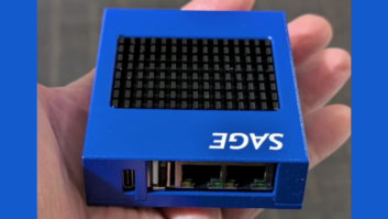
Fig. 1:Regularly check the date and time on your EAS equipment.
With many people installing new CAP-compliant gear, Jim Davis of Radio One Raleigh writes with an idea of what to do with your old box. Connect it up to an off-air air monitor feed and use it as a confidence monitor to ensure EAS tests are sent and received.
In multi-station facilities, many engineers route their EAS signals through switchers and routers where a malfunction might occur.
The confidence monitor’s paper tape will serve as a record of what has been received and what hasn’t.
Jim reminds you to check the date and time on your EAS units periodically. It’s also a good idea to check your receiver operation. Make sure the station is tuned to the correct LP-1 or LP-2 station. Remember you must show your required weekly tests sent as well as those received. If a receiver malfunctions, you may be missing received tests.
* * *
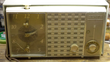
Relay logic, as simple as it is, can cost you a lot of troubleshooting time. Project and contract engineer Joe Stack paid homage to the relays, shown in Fig. 2.
A phasor controller on which he had the opportunity to work started intermittently to mute the transmitter RF output only when switching to day pattern. Night pattern was fine. All indicators for the contactors in the phasor and all tower doghouses were lighted. This indicated that those devices were switched into the proper mode. Still, there was a day interlock open somewhere.
(click thumbnail)
Fig. 2: Periodically tighten screws on phasor controllers. This view is looking down on a relay drawer that has been pulled out.

In this situation, we might suspect a bad relay. Joe followed this route and found all relays operating properly, except for the RF mute relay. When Joe inspected, he discovered that the screw terminals on three relays were loose (and as a result, so were the wires). These terminals were connected up to the latching contacts that connected the 24 V DC interlock voltage through to the transmitter RF mute relay.
After finding this, Joe went through all four phasor controller rack drawers and checked the tightness of all the relay terminals, just in case. Even a small amount of vibration can cause relay socket screw terminals to loosen eventually. The problem starts with intermittent operation and ends with failure.
Even if you have a full schematic of the phasor controller, Joe suggests you sketch out a block diagram or flow chart for each phasor mode you need to troubleshoot. It dramatically cuts down the number of relay contacts visible to you. (When troubleshooting, put stuff you don’t need to see out of sight when you can; distractions only cloud the picture.)
When Joe is finished he puts his reduced diagram in his site documentation binder, noting the problem and solution, initialed and dated. Later, should something similar arise, he or the person responsible then will know what happened. Joe adds: Beware of 220 VAC in some phasor controllers. This may exist along with the 24 VDC relay voltage, so watch your fingers.
Fig. 2 shows just Drawer No. 3 of the phasor controller, which also contains the main 24 V DC power supply and spare power supply. There are 17 relays in this drawer. Each is mounted into a socket that brings the relay coil and contacts to screw terminals on the sides of the relay socket. There are 80+ relays within the four drawers of this particular phasor control system.
Years ago, I was called to a site where the phasor controller was not functioning. All equipment was new, which made me wonder what could be the problem.
On the floor of the phasor cabinet were all these shiny nickel-plated screws. It turned out that the vibrations caused by multiple contactor switch cycles, as the engineers ran their RF proof measurements switching from day to night modes, loosened many of the screws. Eventually enough fell out that the controller ceased to function.
Joe’s suggestion is to look first for the simple problems. Even the vibrations caused by heavy RF contactors switching twice every day will cause screw contacts to loosen. With the station and AC power off, tighten these terminals at least once a year.
* * *
Do you use an outside frequency calibration service to keep tabs on the accuracy of your operating frequency? If so, drop me a line with the name of that company and their contact information. If you make these measurements yourself, let me know that as well. We’ve had inquiries from engineers searching for this service. Let’s see if we can help!
* * *
Marc Mann notes a video on YouTube that shows a square-hole drill bit in action; Radio World also noted the video in a recent NewsBytes email. Engineers who worked for hours with an aluminum nibbling tool and a small file, to achieve consistent square holes for pushbutton switches or indicators, will appreciate the efficiency and accuracy of this device. But, Marc adds, it won’t fit in your tool bag. Go to YouTube, key phrase “square hole drillbit.”
Contribute to Workbench. You’ll help your fellow engineers and qualify for SBE recertification credit. Send Workbench tips to [email protected].