I’m going to go out on a limb here and start with a statement: In the real world, there is no such thing as a non-directional FM broadcast antenna. An isotropic radiator may be theoretically possible, but as soon as you connect a transmission line or mount the antenna, the field is disturbed and the antenna is no longer isotropic.
It has been recognized since the earliest days of FM broadcasting that the interbay transmission line, the feedline, the mounting structure, lighting conduits, nearby guy wires and anything else metallic in or near an antenna’s aperture will have an effect on the horizontal radiation pattern. In a nutshell, that means that every FM broadcast antenna is a directional antenna, at least to some degree.
That is a well-known phenomenon and the FCC is certainly aware of it. The agency still classifies FM antennas as non-directional that are not “directionalized” with parasitic radiators and other devices. A broadcaster can license as non-directional an FM antenna that he hangs on the side of a fat tower even though that mounting arrangement will most certainly produce considerable distortions in the horizontal radiation pattern.
For decades, engineers have been taking advantage of this, with the full knowledge and consent of the FCC. Over the years, in the process of ordering, assembling and installing new antennas, I have ordered range studies of the antennas using a mock-up of the environment in which the antennas will be installed.
STUDYING THE PATTERNS
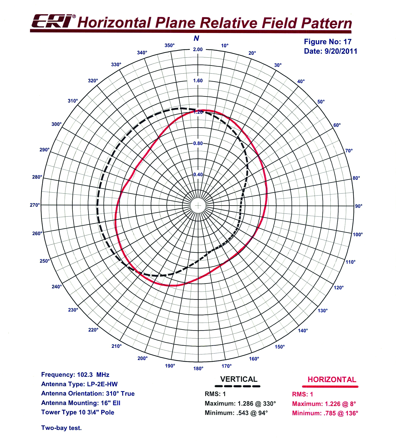
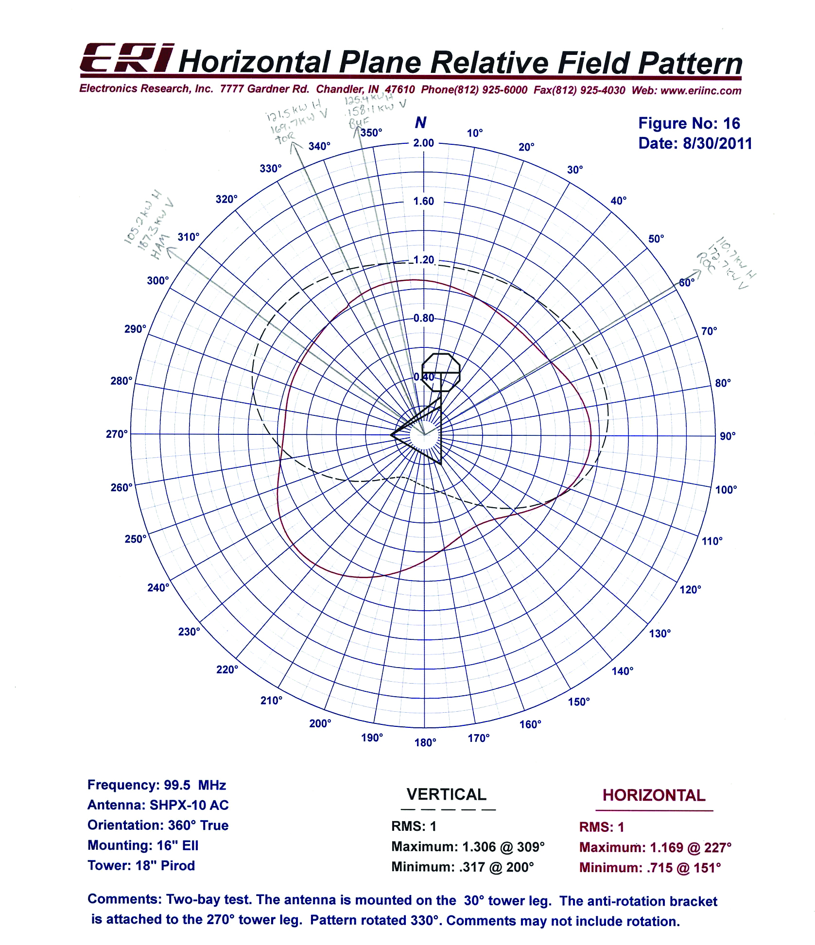
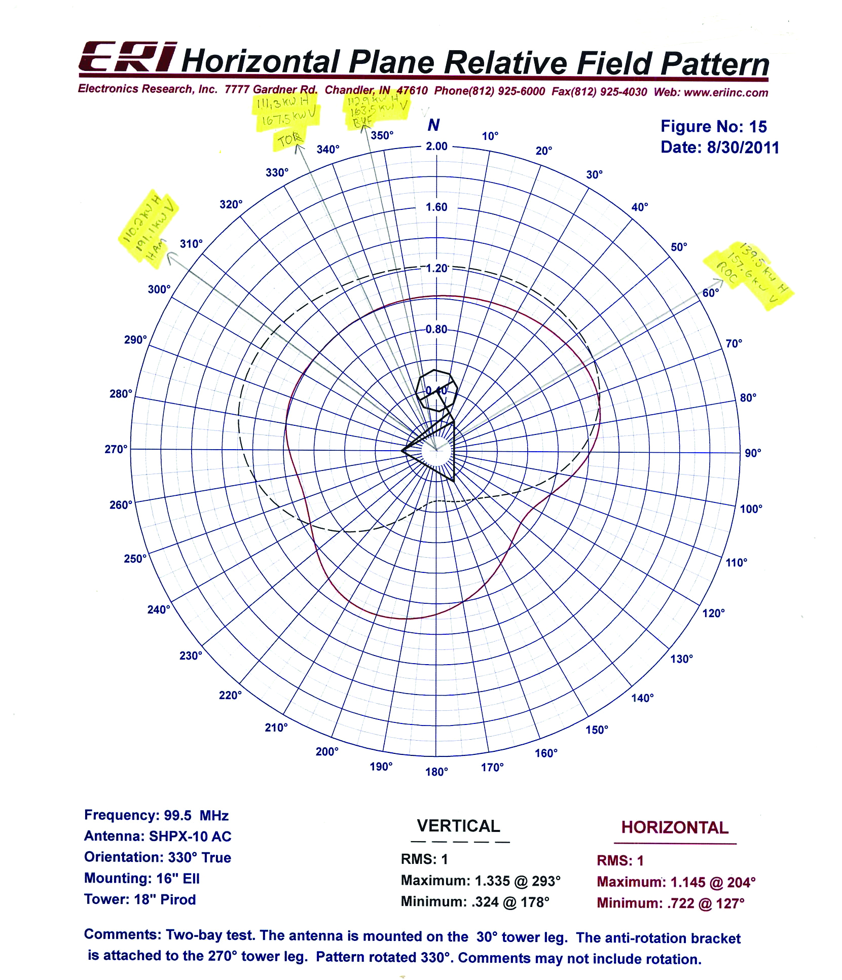
This process starts with mapping the tower in the vicinity of the antenna and accounting for legs, flanges, diagonals, horizontal supports, conduits, transmission lines, ladders, climbing pegs, guy wires and anything else that might have even a small effect on the radiation pattern. That information, along with detailed photos, is sent to the antenna manufacturer where that mounting environment is reproduced on the antenna range. A single bay of the antenna is then used to measure the directivity of both the horizontally- and vertically-polarized components of the horizontal radiation pattern.
If the antenna is to be mounted on a tower section, several different mounting orientations and arrangements may be measured. For example, leg mounting with three (or more) different orientations and face mounting with a single orientation. If the antenna is to be pole-mounted, a single orientation may be measured.
A set of pattern plots, usually composite plots showing both horizontally- and vertically-polarized patterns on each plot, is provided back to the engineer. He or she can then use that information to choose an antenna orientation that will produce the strongest signal into areas of desired coverage.
In some cases, parasitic elements may be added to make the radiation pattern more circular, a process which is sometimes called optimization. To my knowledge, this is the only way parasitics can be used with a non-directional antenna; all other uses of parasitics would make that same antenna “directional” and it would have to be licensed as such.
AN EXTREME CASE
None of the above is new, so why am I writing about it now? It’s because of a recent case in north Texas where, according to the FCC, an FM station licensee used mounting structure distortions of its FM antenna along with parasitics to produce a highly directionalized “non-directional” antenna pattern in order to maximize its signal into a large market to the southeast.
The resulting directivity reportedly produced a gain of 4.385, a maximum-to-minimum power ratio of 19.8 dB for the horizontally-polarized component and 11.2 dB for the vertically-polarized component. The maximum relative field values for the antenna as installed are reported to be 1.62 and 1.657 for the horizontally- and vertically-polarized components, respectively.
All this, according to the FCC, produced impermissible overlap of the offending station’s interfering contour with a co-channel neighbor’s protected contour. With almost 2.75 times the authorized non-directional power being radiated in that direction, no one should be surprised that interference was taking place.The FCC has issued a show-cause order to the offending station ordering the licensee to show why its license should not be modified to make the facility “directional.” This modification of license would result in a power reduction so that the maximum relative field value would equate to the class maximum of 100 kW ERP (in this case, that works out to a little over a third of the present TPO, all other things being unchanged).
[Subscribe to Radio World Engineering Extra]
I am not going to make any judgments on what did or did not take place in the Texas case. I have read the very lengthy correspondence file including the pleadings on both sides and both have valid points. At the end of the day, however, I think that non-interference has got to rule.
The licensee of the offending station has since responded with a commitment to remove the parasitics and mount the antenna in a conventional way so that the extreme distortions to the non-directional pattern are not created. It remains to be seen how the FCC will respond, but I would think this should be acceptable (but perhaps with some verification required by photographic evidence, a pattern study or both).
This case is important for FM broadcasters because it represents the first time that the FCC has ever made an issue out of “inadvertent directionalization” of an otherwise non-directional FM antenna. It represents the first time, to my knowledge, that the FCC has proposed “the involuntary modification of a licensed and operating non-directional FM station based on a conclusion that the station’s particular antenna pattern is functionally directional.”
A VAGUE DEFINITION
In his response, the licensee correctly states that this comes out of the blue, following “three decades of commission silence in the area of side-mounted and ‘optimized’ FM non-directional antennas.” He further points out that there are no published standards for evaluating when a non-directional antenna would become “too directional.”
Perhaps the biggest danger here for FM broadcasters is that this FCC action sets a precedent without defining the boundaries. It reminds me of something Supreme Court Justice Potter Stewart once said about pornography, stating that it is hard to define, but “I know it when I see it.” If that’s the kind of vague definition that the FCC is applying to inadvertent FM antenna directionalization, we’ve got a real problem.
The licensee of the Texas station asks in its response to the show cause order: “Will the [FCC] also investigate and potentially reclassify the hundreds or thousands of other stations with side-mounted FM antennas?” A very good question indeed.
So what are FM broadcasters to do? I think the most important thing is common sense: Don’t take any extraordinary measures to directionalize an antenna. Whatever antenna mounting schemes we employ should be defensible and in accordance with practices throughout the industry. There should not be much argument from the FCC or other broadcasters if your antenna is mounted in the same manner as hundreds of other antennas using the same brackets and hardware.
One other thing that evidently (from the Texas case) can hurt you is to make pattern studies that show significant distortion of an antenna’s pattern with certain mounting arrangements. Some good advice is don’t create evidence against yourself!
Does all this mean that the days of mounting an FM antenna so that the best signal is produced over a certain geographic area are over? I don’t think so, as long as we are careful and keep things within reason.
Read an important update to this story here.
W.C. “Cris” Alexander is director of engineering at Crawford Broadcasting Co.