It has been said that AM antenna systems are living, breathing entities. Just like a person or pet, each has its own personality, behaviors and idiosyncrasies. While the theory behind each antenna may be similar, they are individuals in their own right. No two are the same.
The inside of an ATU or phasor should be clean. Let�s face it: Nobody really likes going to the doctor. The person in the white coat is probably going to tell you what you have done wrong in the past few months, and hopefully, we, in our own way, will listen to the advice and take the necessary corrective steps. Not only should these visits keep your health on a straight and narrow path, but they also will provide a baseline of data where trends can be easily identified and addressed before the occurrence of a catastrophic event. However, even with the most fastidious approach, things can and do go wrong.

The AM antenna system really is no different.
This month, we will look at the maintenance and troubleshooting of AM antenna systems. We are not going to delve deeply into the mathematics and theory; that topic requires multiple tomes of sagacious knowledge. The hope is that even the AM antenna neophyte will be more comfortable maintaining an AM antenna after reading this. In the end, a high degree of comfort will conserve scarce resources, and when a problem does occur, make the treatment more efficient.
The first step in any AM maintenance program should be the acquisition and preservation of historical data concerning the array. If diligent logs have been kept by your predecessors, then spend an afternoon reviewing this documentation. Look for any historical issues that may have plagued the antenna previously, including seasonal trends. If no such documentation exists, then it is not too late to start your own log.
Record a full set of transmitter parameters, paying special attention to forward and reflected power. On the antenna side, record the crank settings on the phasor, phase monitor readings, common point and base currents, and check to ensure that coils in each stage of the antenna system are marked as to tap location. After recording this information, make a general walkthrough of the plant taking care to observe any locations or potential locations of damage and weathering, or unusual happenings. Finally, run the monitor points and record their values.
This information provides a snapshot of the condition of the antenna system. The data should then be compared against the prior proof of performance and the parameters listed on the license. Variances from the licensed data should be noted and corrective action taken, if necessary.
But do not start blindly turning cranks or moving taps, and above all, do not panic if issues are noted. Nowhere is this more true than with monitor points exceeding their authorized limits. While that condition can get you into trouble with the commission, a high monitor point is not always a call to action for aggressive array tweaking. Quite simply, some problems can be caused by strange phenomena and pursuing� a logical systematic approach to the apparent problem will tend to present a solution quickly.
SOLVE PROBLEMS
When inspecting the inside of a phasor, the transmitter power should be turned off. The common point current, monitor points, phase monitor readings and base current ratios all work together to illustrate what is transpiring. In the case of the non-directional antenna, the number of measurable parameters is reduced, but so is the complexity of the potential problem. A significant variance in one parameter is not necessarily indicative of a major antenna issue.

The common point is the location where all of the branches in the antenna system come together at the phasor input. This point always has a strange impedance; therefore a trim circuit is employed to bring the impedance back around to something that the transmitter will like. Since solid-state transmitters are usually designed to operate into an impedance of 50 ohms, most common points will have that value of resistance, and maybe an ohm or two of capacitive reactance to balance out the inductance caused by the tubing in the cabinet.
A variance in the common point impedance will tend to result in high reflected power at the transmitter. This can be confirmed by operating the transmitter into a dummy load. If the high VSWR condition disappears, then certainly the issue is in the antenna system. A high VSWR condition, and by extension a change in the common point impedance, does not necessarily mean the pattern is �out.� If the phase monitor agrees with the licensed values, but the high VSWR condition persists, the first item to check would be the common point trim circuit and the integrity of its components. If no issues are identified here, then we must dig deeper.
The current ratio indicated on the phase monitor should be within 5 percent of the licensed value, while the indicated phase angle should vary by no more than three degrees. If a significant variance is observed, rule out a problem with the phase monitor. To do this, take the reference tower sample and connect it to the appropriate phase monitor input through one leg of a tee. On the other leg of the tee, connect a short cable and then look at the other inputs of the phase monitor individually. You should see a current ratio slightly less than that indicated on the reference tower input and a lagging phase of a degree or two. Note that since you are splitting the signal two ways, the reference level pot on the phase monitor will have to be readjusted to get a 1.0 sample value.
If the phase monitor values agree with each other, then check the sample lines for damage, opens or shorts, as well as the sample loops or torroids, depending on the array configuration. For torroids, a test jig can be created where the torroids are mounted side by side for comparison. A single piece of copper tubing provides the source, and passes through each of the toroids. Remember that many toroids must be terminated if a source is present, otherwise they will fail; so do not forget 50 ohm loads for the components not being tested.
If phase monitor readings continue to show problems with phase or ratios (and if you know the monitor itself is working fine), then a real problem may exist with the system.
Further isolation of the issue can be accomplished through the use of current meters. Unfortunately, the commission removed the base current reading requirement for directional antennas, and many stations have allowed this tool to fall into disrepair. Base current ratios provide a third crosscheck on system health, and their importance should not be overlooked.
Nonseasonal changes in the actual base currents, with measured ratios in tolerance, may be indicative of a ground system issue under development. If the ratios change, and the meters are all known to be accurate, then a shift in the pattern has probably occurred. A very low base current at one tower may indicate an issue in that portion of the system, such as component failure or transmission line damage. To isolate the issue further, work backwards.
Most antenna systems will have jacks at the inputs to each ATU, as well as the output of the phasor at each transmission line. Checks of the currents at these locations will likely help to further isolate the problem. Current at the phasor output, but not at the ATU input, probably indicates a problem with the transmission line feeding that tower. Current at both locations, but not at the tower may point to a low impedance path in the ATU or with the tower itself. Through a logical approach, the other possible permutations can be considered and the potential location of the failure identified.
Once a general location of the problem is identified, component level troubleshooting may need to be employed. Careful visual inspections may be made when the station is operational, as may checks with infrared thermometers or cameras if heating is suspected. However, any testing that requires physical contact or temporary removal of a suspect component must be performed only after the transmitter is shut down and properly locked out.
For inductors and coils, the surface should be clean, with no significant changes in appearance or coloration relative to other similar components. Taps should snugly fit on the individual turns, and in the case of variable inductors, the wipers should make good contact with no deformation or damage. While examining coils, look for signs of arcing that may be hidden. If it is necessary to move a tap or a crank, be sure to visibly mark the current location so you can return to it.
Capacitors tend to hide their issues. Visible copper in vacuum capacitors should be clean and shiny; discoloration is an indication of either oxidation (which will not happen in a vacuum) or high-voltage damage. Mica capacitors should not have any odd bulges or cracks in their surface. All capacitors should be value checked through an LCR meter, or preferably an RF bridge. Components with values outside the tolerance range should be replaced. Additionally, bridge measurements returning more than a couple of ohms of resistance should also trigger a replacement.
Static drain chokes will provide continuity to ground at DC but will present very high reactance at the frequency of operation. This mimics an open circuit, rendering them essentially invisible at the frequency of operation. A visual inspection of these components may identify or �dings� in the windings, which can reduce the reactance and render them useless. Similarly, lighting chokes bring the AC across the base insulator by providing a very high reactance value at the frequency of operation, but one that is low at 60 Hz. Verify that these have not failed.
One tip that will go a long way is cleanliness. Both the site and the components should be kept clean and free of debris. Cabinets should be inspected regularly to prevent colonization by vermin, and any uninvited guests removed with access points sealed.
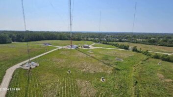
Tower bases must be kept free of foliage and should be covered with crushed rock or gravel. The remainder of the site, especially where the ground system exists and wiring and transmission line run, should resemble the fairway at a golf course. Under no circumstances should trees and dense shrubbery be permitted to grow in these areas, as this will result in long-term damage and degradation to the antenna system.
In the end, the AM antenna is a paradox, but the combination of troubleshooting knowledge and historical data will allow a logical progression to be followed. Sure, that 3 a.m. call will still stink, but it won�t strike terror into your heart.
Ruck is the principal engineer of Jeremy Ruck and Associates, Canton, III.
