Parasitic radiators
Oct 1, 2000 12:00 PM, John Battison
A radio engineer’s definition of a parasite might be something that obtains its power from another’s energy. In other areas of broadcast engineering it might be obnoxious RF signals that are developed in an otherwise stable RF amplifier, resulting in off-frequency operation. There are two general radiator cases for discussion: unintentional and undesired, and desired.
Harmful parasitics Undesirable radiators are those that appear in the close fields of AM and FM transmitters. Almost any tower can cause havoc when located near an AM radiator. In the case of a non-DA station, such an unwanted device can at the very least distort the service area and, depending on circumstances, cause severe loss in a listening area.
In the case of a directional station, a wild tower, one that is not part of the array, can affect the pattern severely, put monitor points out of tolerance and, when close to an array, can cause changes in operating and common point impedance. These undesirable effects often happen without warning with the current trend of mushrooming wireless towers of 200 feet or less.
Another type of tower that often springs up with even less warning is the lower-voltage power line. These towers are usually made of wood and are probably not taller than 100 feet. During one project, on which I specified the location of a client’s two tower array, the client noticed a new power line going into place just along the edge of the site just as the transmitter was being installed . When we arrived to proof the array, the line was almost complete. Needless to say it was impossible to meet the maximum expected operating value (MEOV). This was in the days before standard patterns. Each 80-foot pole had a solid ground wire running down its length. At 1600kHz, the poles reradiated horribly and completely ruined both the non-directional and directional patterns.
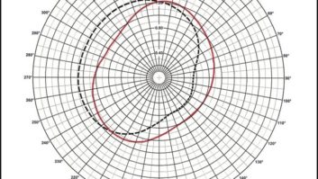
Power companies never permit a break in the wooden pole ground wire, and it is almost impossible to persuade these utility companies to change a power line’s planned route. Fortunately, power line RF chokes can be inserted at the bottom of the ground wire. The DC circuit still meets the power company’s requirements while providing the station with the necessary RF break in the line. In the installation I mentioned earlier, we used a number of these chokes and split the cost with the power company. Once installed, we obtained a nearly circular non-directional pattern.
Taller towers and structures can also be a source of reradiation. The process of detuning these structures is complicated and will be the subject of a later column.
For FM, troublesome reradiators are normally found very close to the antenna and are probably a part of the antenna supporting structure. Such problems are usually solved by the antenna and the tower manufacturers’ cooperation. As a general rule, FM transmissions are usually not subject to the same unexpected intrusion of a closely spaced tower. When an FM antenna will be placed on an existing tower or located within short distances of other antennas, the antenna consultant will usually take care of such matters. Towers with candelabras are a typical example.
The FCC has never been very enthusiastic about undriven parasitic arrays for AM transmitters because of problems of stability. Where a radiator is driven by an established combination of current and phase there is little likelihood of sudden large drive changes taking place, which could drastically alter the pattern.
A parasitically driven element derives its power from the driving antenna. Therefore, even a small change in the power supplied to the driven tower could make a large change in the current and phase of the parasitic element. Naturally, the current developed in the parasitic radiator falls off rapidly as the distance between the two towers increases.
On the other hand, the phase in the driven tower increases with separation. A small degree of phase control, about 40 degrees, is possible by changing the length of the parasitic tower. However, this often reduces the current in the driven element and makes operation more difficult. A small amount of control can be obtained by means of an L/C circuit at the base of the parasitic tower, but the system is still normally regarded as being less stable than a driven tower.
Reflecting elements All radio engineers are familiar with Yagi antennas. In this system, a quarter-wave active antenna is connected directly to the receiver, and a slightly longer reflector element is placed approximately one-quarter wavelength behind the antenna. A slightly shorter director element is placed about one-quarter wavelength in front of the antenna. About 8dB or 9dB is the maximum gain obtained from this type of antenna. Because of the small element size, half-wave elements are commonly used in these antennas. A Yagi tends to exhibit narrow bandwidth as a result of its directivity.
Some interesting results can be obtained by using very tight spacing between the radiator and the reflector. When this is done the reflector no longer behaves as a reflector and becomes a driven element because of the high current induced in it due to of the close spacing. One example of a Yagi directional antenna is found in AM directional arrays today, but they are either all driven (not parasitic), or purely directors and reflectors. Typically referred to as in-line arrays and comprised of up to six towers, the system bandwidth can decrease and overall efficiency may be low.
Several station owners have wondered why they could not make a DA by dropping a wire from a guy wire. Usually there is not enough room, but the FCC has approved at least one. At one time, WKYC in Cleveland needed to reduce radiation towards Canada while using the TV tower as an AM radiator. The plan was to drive the drop wire on the Canadian side to reduce radiation.
It was found that driving the drop wire did not reduce the radiation in the Canadian direction sufficiently. Eventually, a resistor was placed on the ground end of the wire to reduce the radiation. I don’t know if the FCC would accept this type of radiation control today. However, several consulting engineers have suggested that greater consideration be given to the use of drop wires from guy wires.
Nevertheless, the idea has merit, especially for AM stations located on small non-expandable antenna sites that need to directionalize to improve service or to provide protection. A simple two-tower DA could easily be designed for daytime use. Night vertical radiation requirements might be harder to meet.
The fact that as the parasitic radiator and driven tower move closer together they tend to act as a driven tower because of the very high induced current might make such a project feasible.