FM antennas and radiation
Sep 1, 2006 12:00 PM, By John Battison, P.E., technical editor, RF

When broadcasting was in its infancy, amplitude modulation (AM) was the principal modulation system being researched and developed. Once efficient generation of useful RF signals was discovered and larger transmitter power output stages were developed broadcasters had to find an efficient radiator.
Horizontal wires, vertical wires and poles, loops, flat-top tee antennas and various other configurations were used, but it became apparent that the vertical antenna, whose height was determined by the operating frequency, was the most efficient and easiest to use. It did not suffer from undesired directional characteristics and it produced vertically polarized radiation, which was soon accepted as preferable for AM and its ground wave characteristics.
Throughout the years the vertical antenna with various modifications has become the standard for AM broadcasting. In recent years broadcasting efforts have been directed toward reducing the height of the vertical antenna, with considerable success. With the introduction of the Kintronic Labs Kinstar antenna radio has probably reached the peak of AM antenna miniaturization, after about 100 years of work.
On the other hand, the FM antenna has developed from knowledge of radiation gleaned mostly from AM and amateur radio antenna technology. Prior to World War II, a comparatively small amount of work occurred in the development of higher frequency antennas. Military usage was frequently confined to the dipole or folded dipole, steerable directional antennas and occasionally a loop.
For higher frequency transmitter operation various modifications of rhombic, curtain and other directional antennas with electronically steerable beams were developed for shortwave commercial radio. The prewar development of TV, with its need for greater bandwidth, opened the VHF and UHF bands. Then the plethora of UHF, radar, communication and detection equipment developed by the military in World War II widened the field.
Moving ahead
Work by Major Edwin Armstrong resulted in the first commercial FM broadcasting on the low band. But then World War II cut off experimental broadcasting and further development of its associated equipment. At the end of World War II the FCC doubled the authorized frequency slot assigned for the commercial FM band (88.1MHz to 107.9MHz) and the radio world expected to see commercial FM take off. Many new shapes and sizes of FM antennas and transmitting equipment were soon on the market. But, as we all know, FM progressed rather slowly.
Because of the differences in propagation between the AM and FM frequencies, antenna requirements for the new FM service were vastly different from the old AM system. In AM the distance to the service contour for a given power is mainly controlled by the ground conductivity and the operating frequency.
In FM the distance to the service contour is controlled mainly by the height of the antenna above ground (elevation above average terrain), ERP and lack of intervening obstacles. �Line of sight� is the major requirement.
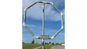
Most AM transmitters require tall vertical radiators and it is fortunate that vertical polarization is the preferred choice. FM antennas are relatively small but efficient. Therefore, radiating systems can employ either horizontal, vertical or circular polarization. Because of the higher frequency, and consequent smaller size, many FM antenna designs are possible.
Early FM
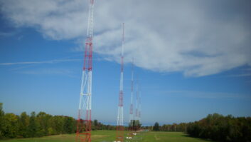
When FM broadcasting first commenced the FM antenna was mounted on a tall tower many feet above ground. It became obvious that existing AM stations could mount their FM antennas on top of their AM radiators and avoid the expense of additional towers. Many original FM antennas were designed as top-mounted radiators, which should produce a fairly uniformly circular radiation pattern. However, sometimes it became necessary to side mount an antenna because of overall tower height restrictions or other technical problems.
The AM transmitter operators were already aware of the problems of pattern distortion caused by closely adjacent vertical structures within the high field area of an AM radiator. This has become an increasingly difficult problem for FM operators. When small FM radiators are mounted a few feet from the face of a tower the original basically circular pattern of the FM radiator will be distorted by reradiation and reflections from the tower. Consequently, a coverage pattern far different from the expected may result.
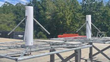
Another point of difference between AM and FM broadcasting is the amount of horizontal real estate required by an FM antenna regardless of whether it is nondirectional or highly directional. Twelve tower arrays are not required, only a suitable supporting structure that will carry the desired number of FM antennas and will not conflict with EPA non-ionizing radiation requirements.
The nondirectional AM station may have areas within its service contour where there is excessive interference, there may be areas of low signal level due to the presence of large metallic objects and there may be skywave interference. A directional AM station may have additional problems due to new construction that distorts its anticipated service contour.
As radio broadcasting has progressed and FM finally came of age, automobile listening increased and is more used than AM today. The higher frequency (shorter wavelength) signal is susceptible to spurious reradiation from almost any metallic object within high signal level areas. Distant ground features, buildings and terrain can cause trouble through reflections and reradiation that interferes with the desired signal. A particularly irritating form of interference is picket fencing. This causes the desired signal to vary in signal level and sound like it was being received through a picket fence.
The terrain in the area of the FM transmitter is extremely important. Reflections from tall buildings and mountainous areas, as well as intervening large bodies of water, can produce interfering signals from several; this is known as multipath.
As our experience with FM has grown and our knowledge of high-frequency propagation has increased a large number of valuable technical service programs have become available.* Anyone who plans a new FM station should avail himself of one of these programs. A properly prepared and executed propagation/coverage program will frequently expose unexpected areas of poor reception from what otherwise appears to be an excellent site. This precaution can save a great deal of expensive site error correction after construction.
E-mail Battison at[email protected].
* A survey of available transmitter siting and coverage software programs appeared in the March 2006 issue of Radio magazine.