The Phasor
Nov 1, 2009 12:00 PM, By John Battison, P.E., technical editor, RF
Over the nearly 80 years that have passed since the first AM DA was built in this country, the state of the art has progressed slowly but steadily. The FCC’s engineering department coped well with the new challenge, and through necessity developed a set of engineering rules establishing a method of proving that the completed antenna systems produced radiation patterns similar to the proposals made in the original Forms 301.

Providing the information the Commission required became an expensive proposition and quite possibly resulted in a few less-directional stations being constructed. As the proposed operations tended to become more exotic, a lot of thought was expended on developing a more convenient method of proving a directional antenna pattern. In 2008 the industry’s efforts were rewarded and the FCC approved the new simplified directional antenna proof of performance program. Gone now are the mandated expensive, time-consuming and occasionally dubious, lengthy radial runs. In their place is what has become almost a computerized proof. The new DA proof of performance requirements have already been broadly described and discussed; however, the new reduced actual field measurements still entail a minimum amount of actual measurement. These measurements, plus a number of very accurate system measurements, combine together to prove the working directional antenna system’s compliance with Form 301.
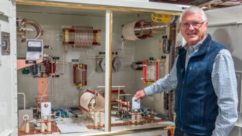
Heart of the antenna system
The phasor is basically the heart of the AM directional antenna system. This unit, together with other circuit items such as antenna tuning units (ATU), accurately calibrated instrumentation and accurately cut lengths of coaxial cable forms the brain and heart of the DA. Over the past 60 or so years I have come across many different phasors, some were beautiful precision works of art, others were good, solidly constructed work horses and one or two were unbelievable. But they all worked � according to the licenses on the station walls. It seems that with the greater emphasis being placed on the actual system’s measured values of individual units ease and accuracy of measurement should have high consideration in phasor design.
The purpose of the phasor is to direct RF of the required phase and magnitude from the transmitter to the individual towers in the antenna array. This is accomplished by feeding the signal into a power dividing and phasing network system whose name was well known by radio engineers long before �Beam me up, Scotty� was a popular phrase, and with a very different connotation!
We have all encountered conditions at transmitters where one had to be a contortionist to access the desired measurement points. Often it was necessary to disconnect components and devices in order to insert a measuring instrument. Examination of the new rules seems to imply that repeatable readings are an even more precise requirement of an acceptable system. For example, in some critical cases it might be necessary to record the actual positions of the OIB leads and also whether the short or long clip lead was used so as to be sure of repeating the measurements under the same conditions. This sort of statement may seem like splitting hairs but my interpretation of the new rules seems to call for much greater care in making and recording circuit and component values than has sometimes been required in the past.
Perhaps some modifications in facilitating easier measurement of circuit values might be worth considering by phasor manufacturers. The placement of such things as jacks for inserting inline operating bridges and similar devices does not always make for easy accomplishment. Some engineers find that a permanent inline bridge mounted at the phasor input common point is very convenient. It certainly is, but it confines bridge use to that one circuit. To facilitate OIB flexibility it might be worthwhile locating a common point input jack on the front panel of the phasor with adjacent provision for supporting the bridge during measurements. Such an arrangement would require a removable insulated cover at the access jack for the OIB clips, but it would obviate the need to disconnect the input cable, which sometimes is necessary when measuring common point impedance.
— continued on page 2
The Phasor
Nov 1, 2009 12:00 PM, By John Battison, P.E., technical editor, RF
Inside job
Most engineers have had to open the back of the phasor and connect an OIB to a jack in an individual tower cable. This generally requires opening a phasor door or even occasionally removing a piece of the cabinet. It is not uncommon to find a slight change in the measured circuit values when the cabinet door is closed or the piece of cabinet replaced. I have also noticed this occurs occasionally when opening or closing ATU cabinets in the field. In view of the reliance placed on circuit values and measurements in the new computerized directional antenna proof of performance this may be a point worth considering by equipment manufacturers.
One of the bete noires of many station engineers (myself included) is the tapped inductor. This is a useful device, but in my opinion, in many cases its time has passed. For one thing, positive identification of critical tap positions is comparatively difficult to determine. Nail polish is still good, provided it doesn’t unwittingly interfere with clip connection. But every time it is changed the flexible lead can also move and change reactance values. The actual tap changing also requires transmitter shutdown and reentry into the phasor or ATU. After this has occurred several times while trying to find the correct tap position, a good-enough position may be accepted through laziness or sheer fatigue.
The use of continuously adjustable inductances is preferred. Not only is correct tuning usually achieved more quickly, but precision adjustments can be made very easily via smooth turning panel mounted control knobs. There is no need to open cabinet doors or remove cabinet panels. Excessive transmitter ons and offs are avoided leading to longer component life and generally improved operational economy. Although continuously variable inductors are more expensive than tapped coils, the additional cost is worth it overall.
Even the lonely ATU inductor in a doghouse or all-weather field mounting would benefit from a change to a continuously variable coil. The time may be ripe now for phasor and ATU designers and manufacturers to look at operational flexibility in the design of such equipment. Maybe the upcoming generation of radio engineers will encounter a new ease of measurement as a facet of the Commission’s new directional antenna proof rules.
E-mail Battison at[email protected].