The Silent Partner: Wire & Cable
Nov 1, 2004 12:00 PM, By Chriss Scherer, editor, and Scott Fehl
The next time you have to wire something in your facility, think about what you’re about to do. Will you reach for the standard single-pair, shielded wire you have used for the past 25 years without considering what it will do to the signal? With the proliferation of digital audio sources and Ethernet routing, you probably keep two or three types of wire available at all times. While it all may seem like copper strands, there are real differences in wire, even between types that are supposedly for the same purpose.
No one paid attention to the wire being used when all the signals within a facility were baseband analog audio and low bit-rate data. These low-impact uses are not as easily affected as today’s high-bandwidth signals. Paperclips and zip cord may pass a signal, but not over any distance with any reliability.

Choosing the best wire for the job is important, but there are realistic limits that can be achieved. The mechanics and physics of a wire or cable are important. I’m not suggesting that you remove all the existing wire in your facility and replace it with some oxygen-free, helium-rich, deuterium-encased boutique wire. That isn’t necessary. However, there are considerations that are likely taken for granted.
While wire is a passive component in an installation, the wrong choice can introduce signal losses between the source and destination, as well as introduce possible interference from external noise. The result is lost data and excessive installation time.
The physical basics
There are several operational characteristics that are tied to the physical properties of a cable.
Noise rejection is an inherent trait of a balanced signal if the circuit balance is maintained. The quality of the shielding � if one is used on the cable � and the consistency and tightness of the twist of the wires affect the noise rejection capability.
In general, the cable should have a high number of twists for a given length. A cable’s noise rejection capability will increase with more twists that are consistent and tightly maintained.
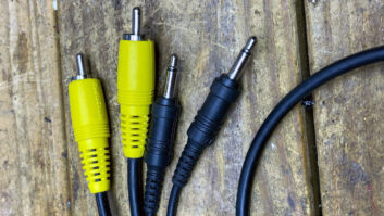
Shielding is most effective for EMI and RF rejection. The two most popular forms of shielding, both of which are effective, are braided and foil. Braided shields have excellent rejection and flex-life, while foil shields are more cost effective and offer the best high-frequency rejection. A foil shield is also often easier to terminate.
Attenuation is the loss of signal. The longer the run, the more attenuation the cable will have. The size of the conductor or gauge of the wire plays a significant role in limiting attenuation. For long runs, 22 or 24 gage is better. However, if you are soldering to a multi-pin connector or patchbay, 24 or 26 gage is the best choice.
The type and amount of dielectric also affects the loss in the cable. As the signal travels through the copper conductor it is absorbed through the dielectric and into the shield. The dielectric is the insulation that coats each conductor, which electrically separates the conductors from each other and the shield. Signal absorption is more pronounced at higher frequencies. The lower the dielectric constant and the thicker the insulation, the less signal will be absorbed. This absorption is caused by capacitance, so a lower capacitance will also result in less absorption.
Working the medium
Each cable has its own specific physical properties that should be considered. Most permanent installations require using a cable that is UL-listed as flame retardant. Each UL classification has specific standards for flame spread and smoke particle. By using specific types of plastic compounds, the desired UL listing will be achieved.
The construction of the cable affects the speed and ease with which it can be terminated. Drain wires facilitate easier ground termination, while certain dielectric types are easier to strip and have high melt temperatures that reduce wick back. Tinned copper conductors are easier to solder, and certain jacket compounds are easier to strip than others.
One often overlooked characteristic is a bonded shield, where the foil shield is attached to the outer jacket. This significantly reduces the effort to strip the outer jacket. The next time you buy your favorite wire, see if the shield is bonded to the jacket. If it’s not, substitute a model that it is. You’ll be glad you made the change.
Digital bits
Digital signal cables include all the considerations listed above, but have additional unique requirements. The most important one is impedance.
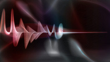
The AES3 audio standard specifies a cable with a characteristic impedance of 110O, �20 percent. While analog audio wire will pass an AES3 signal, that signal will be adversely affected, particularly over any distance. A conventional analog audio cable has a characteristic impedance of 30O to 60O. Digital signals are more like RF, while analog audio signals are more like dc in a given conductor. When a digital signal is passed through a mismatched impedance, internal reflections can develop within the cable. For an AES3 signal, the 110O impedance should be maintained. Figure 1 shows the effect of an impedance mismatch.
For reference, characteristic impedance is different than conventional dc resistance of the conductors. Characteristic impedance is determined by the ratio of the diameter of the conductor, the shield, the thickness of the insulation and the dielectric constant of the insulation.
Bit errors and jitter are caused when the bit becomes unrecognizable or the spacing between bits becomes inconsistent. Impedance mismatches, as mentioned previously, can cause standing waves within the cable. These standing waves cause additive and subtractive interference to the original signal, causing bit errors and jitter.
External interference and cable attenuation can also cause bit errors and jitter.
Digital audio cable should have a bandwidth of 25MHz to effectively be used with sample rates as much as 192kHz. This means that the impedance, capacitance and loss stay within acceptable standards and tolerances up to 25MHz.
Consider a 24-bit sample depth. Added to this sample is an eight-bit header, creating a 32-bit word. Stereo signals are interleaved, creating a 64-bit word per sample. Finally, each bit has leader bit, creating a total of 128 bits per sample. When the resulting 128-bit word is sampled at 192,000 samples per second, the product is 24,576,000 bits per second (b/s), or 24.6Mb/s.
The required bandwidth of a digital audio signal is significantly higher than an analog signal, as the equation above shows: 25MHz vs. 20kHz. A digital cable’s high-frequency attenuation is a critical factor. A lower high-frequency attenuation is desirable.
To reduce high-frequency attenuation, reduce the capacitance of the cable. Capacitance is determined by the type and amount of dielectric (insulation). Digital signal cables often use different types of materials and in greater amounts. Common materials include a foam polyethylene, foam polypropylene or foam Teflon. These compounds have lower dielectric constants (between 1.5 and 1.9, compared to 2.26 and higher in analog audio cable). For reference, the dielectric constant of air is 1.0.
Reducing the high frequency attenuation of the cable will also reduce the rounding of the signal. With enough rounding, the signal will fall below the threshold of being distinguished as a 0 or 1. Again, see Figure 1.
Give a little bit
Digital signal cable can easily be used for analog signals. In fact, digital wire is the best analog wire you can get because of the tighter tolerances.
Ethernet cables operate at even higher frequencies. The twist applied to the conductors plays an even more important role in maintaining signal integrity. The twist should be maintained as far as possible to the connector termination.
Because of the increased use of Ethernet signals, and the application of Ethernet standards to audio, CAT-5 cable has been used to carry AES3 signals. The AES3 signal requires a twisted pair cable with a characteristic impedance of 110O, �20 percent. The CAT-5 Ethernet standard calls for a characteristic impedance of 100O, �15O. This results in a range of 85O to 115O. Compare this to the AES3 extremes of 88O to 132O. Except for the low end, the CAT-5 range falls within the AES3 standard. If CAT-5 cable is used for AES3 audio, it is a good idea to use a CAT-5 cable with a tighter impedance tolerance. A range of �7O works well.
Fehl is product and marketing manager, Gepco International.
Resource Guide
A list of wire and cable manufacturers
Altinex
800-ALTINEX � www.altinex.comBelden Wire and Cable
800-BELDEN1 � www.belden.comCanare
818-365-2446 � www.canare.comClark Wire and Cable
800-222-5348 � www.clarkwc.comGepco International
800-966-0069 � www.gepco.comHeil Sound
618-257-3000 � www.heilsound.comKlotz AIS
+49 8106 3080 � www.klotz-ais.comMogami America
800-800-6608 � www.mogamicable.comNemal Electronics
800-522-2253 � www.nemal.comRAM Systems
800-779-7575 � www.ramsyscom.comRedco Audio
800-572-7280 � www.redco.comWest Penn Wire
800-245-4964 � www.westpenn-cdt.comWireworks
800-642-9473 � www.wireworks.com
Braided shield preparation
By Chriss Scherer, editor
Learn a better way to prepare a braided shield for use in a connector. See the article in the Engineer’s Notebook by clicking on this link.