You probably have needed to match impedances and levels from time to time. Perhaps you want to connect a consumer computer’s sound card to your console; or you need to lower a balanced output level to feed that computer’s unbalanced audio input. Maybe you have a mixer with an unbalanced output that you want to use in your radio station or need an additional mic preamp.
Traditionally you have had two choices: Use a matching transformer or buy a commercial product. Both have problems in that they can be expensive, and in the case of the transformer, there is usually loss instead of gain.
Here is a circuit that will both match levels and impedances. It’s very simple — just a dual opamp IC, four capacitors and seven resistors — yet versatile. Its gain can be varied from 1 to 1000 with a single resistor without upsetting the balanced nature of the circuit, and it produces audio that’s very high quality. It runs on bipolar (+/−) voltages between 2.5 and 22 volts (with a 5532 opamp — the recommended one — though you can also use a TLO-82 at up to 18 volts and they are available at Radio Shack). Of course, the higher the voltage, the higher the output capability (for +4 dBu output you’ll want at least a +/− 6 volt supply, and +/− 15 would be even better).
I have used this circuit for everything from a mic preamp to a composite line extender (I have measured it flat from 10 Hz–150 kHz using 1,000 feet of a single pair in a Cat-5 cable, properly terminated). It has vanishingly low distortion, frequency response far in excess of the best transformers available and excellent square wave response (necessary for musicality and transient response).
Most of us have access to a bipolar power supply, but if you don’t, I’ll also show you how to make one using one IC and any DC wall plug-type supply up to 20 volts.
CIRCUIT DESCRIPTION
The circuit works with a wide value of resistors. You use the following formula to determine its gain:
Gain = 1 + value of the feedback resistor in ohms, divided by the value of the shunt resistor in ohms. The feedback resistors are connected between pins 1 and 2 of the opamp integrated circuit and pins 7 and 6, while the shunt resistor is connected between the two negative inputs to the op amps, pins 2 and 6.
Using real-world resistor values as examples, for a gain of 10, you could use 10,000 ohm feedback resistors and a single 890 ohm one between pins 2 and 6, or 4700 ohm resistors and a single 560 ohm. As long as the relationship is maintained, you will be fine. It is important that the two resistors used as feedback resistors be matched as closely as possible, so grab a few and match them on your DVM. Remember, their ultimate value isn’t as important as the match is between them. See Fig. 1 for the schematic.
![]()
The circuit’s input resistance is determined by the value of the two resistors connected between the two opamp’s positive inputs (pins 3 and 5) and ground. In most cases you will want these resistors fairly high (10,000 ohms or more). The exception would be if you actually want to match something. As an example, a dynamic microphone likes to see a load of around 1000 ohms, so two 560 ohm resistors would work well here for a microphone preamp.
One caveat — if you plan to connect this circuit to an unbalanced output such as the computer mentioned above, you will end up tying one of the inputs to ground by definition, and this will cause the circuit’s input resistance to equal one of the two input resistors.
These input resistors also need to be matched as closely as possible.
Matching the two resistors in series with the opamp outputs usually isn’t as necessary unless you are matching to a specific thing following it. For example, in the composite line driver application, it’s desirable to drive and load the Cat-5 cable pair at its actual impedance (approximately 100 ohms), so you would want to use two matched 47 ohm resistors at the output. If you are going to use this circuit to drive an unbalanced input, you will have to connect one of the output leads to ground; use at least 150 ohm resistors on the output and an opamp like the NJM 4560 with higher output current.
You can build this circuit on a project board. Except for the suggested NE 5532 IC, Radio Shack sells all the necessary parts and also plastic cases that have standoffs to mount the board inside the case. If the box comes with a metal cover, I usually tie these to ground. In a high RF environment, I’d suggest using a metal case. In this case, you can use long screws with three nuts as standoffs to mount the circuit board. If you are going to use an external power supply, make sure you put the 220 µf (and 0.1 bypass) capacitors at the point where the power comes onto the board from outside, and then make sure that your leads from them to the power terminals of the amp IC(s) are as short as possible. You should also use either a single point or a bus bar type ground using at least #18 solid wire for the bus bar. I usually make a stereo version of this transformer, which is simply two circuits side by side.
POWER IT UP
If you don’t have access to a bipolar power supply, here’s an easy one to make. Find a wall plug transformer that’s capable of at least 12 volts (up to 20 volts — the higher the better). Be aware that many unregulated 12-volt DC supplies put out far more than 12 volts unloaded — I found one that put out over 19 volts. Radio Shack sells an IC called the LM386 for $1.99. These work perfectly as a power supply splitter/active ground driver. Simply connect the plus of the wall transformer to pin 6, the minus to pin 4 and use pin 5 for the circuit ground. Leave all the other leads on the chip floating. See Fig. 2.
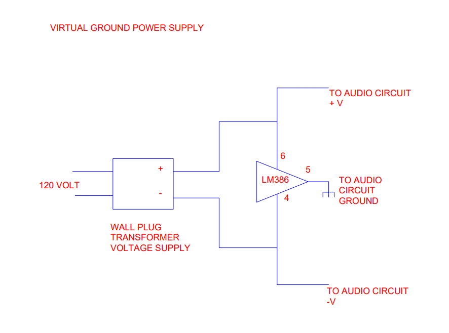
You’ll also connect the transformer wall supply’s plus lead to pin 8 of your dual IC opamp and its minus to pin 4. This circuit is known as a “virtual ground” circuit and provides excellent audio fidelity. To give credit where it’s due, I first discovered it used for audio in Bill Sacks’ Straight Wire Audio PS-2 power supply. The only rule is the power supply must be floating (a transformer wall plug supply, batteries, etc. satisfy this requirement). When I build these units I normally put the LM386 in the middle of the project board with the left and right dual IC opamp on either side.
PROTECT IT FROM HARM
One more thing: If you plan to use this circuit to feed or receive audio from outside, you should put a pair of back-to-back 12–15 volt zener diodes between the inputs (if receiving) or the outputs (if sending) for lightning protection. These will not affect the audio and can even go outside the cabinet.
I hope that you find this circuit handy — I have built them for various things and always been satisfied with their performance. Last week, I built a stereo pair to replace two 111C repeat coils wired 150/600 at the end of a Cat-5 stereo dry pair running between the WGLS-FM studio and their STL site 800 feet away. I terminated the pairs at 100 ohms. The difference in quality was so dramatic that I built and installed a second set at the studio end, replacing an ATI transformer out stereo line amp (which cost about $500). Again, we heard a big improvement in our on air audio. With 111C coils running about $130 apiece on eBay, you can build a stereo pair of these for far less than a single 111C costs, and have far better audio quality as a bonus.
Dana Puopolo is chief engineer at WGLS(FM), Rowan University in Glassboro, N.J.