The bane of FM broadcast transmit antennas has to be the element deicers. To quote one major manufacturer, “I hate deicers. They are the source of almost all my FM antenna customers’ dissatisfaction.”
Since element icing changes the antenna’s impedance (usually for the worse), causing VSWR problems, adequate deicing in cold weather is important for staying on the air with a quality signal. If anything, the problems engendered are worse when the station operates in FM IBOC with digital sidebands.
All FM deicer systems are electrically powered. Two schemes are most often encountered: strip heater units inside the elements and utilizing the elements themselves as heaters.
The former variety — the most common — has insulated coil-type heaters inside each metallic element. Sometimes heaters are integrated into the matching components as well. The heaters warm up the antenna enough to keep ice from forming directly on the antenna element.
The latter scheme steps down the normal utility power line voltage to a very low voltage (something like 3 volts) and allows this voltage to travel through the low resistance of the antenna element(s) creating a large current flow, which even in this tiny resistance generates heat.
This scheme is enhanced when the designer uses a higher resistance metal (such as stainless steel) to form the element, covered with a lower resistance coating (such as copper) on the outside to direct a larger proportion of current through the skin, maximizing the heat on the outside of the element.
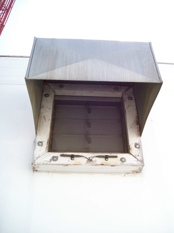
Radomes are sometimes used to eliminate almost all icing on the antenna elements. But ice can damage radomes and, if the ice is bad enough, it will still produce some signal problems in spite of the radome. In really hostile environments, hot air is introduced into the radomes to minimize icing. Since these phenomena are even more notable at satellite frequencies many, if not most, satellite dishes have some form of deicing.
As we often mention in these pages when discussing electrical power systems, high manufacturing standards and processes have produced electrical components that require little maintenance. But they are not maintenance-free.
Deicers are no exception. When deicers are new and known to be perfectly functional, take the time to record the current the system consumes when operating normally. No other piece of information will be as helpful in evaluation or troubleshooting when you need to perform maintenance. An accurate current probe is the best device for this measurement. A good probe that is immune to strong RF fields is essential when measurements are taken at the transmitter. Cheaper units often display some of the induced site RF as line current.
A part of your site preparation for winter should always be a check of the deicers, including a confirmation that the system is drawing the proper current. A lower current always indicates an open heater or even multiple open heaters.
Under Control
A deicer is an electrical device, and thus a potential point of failure. The potential of failure is heightened by use, so it’s best to use them only when needed.
In its simplest form, manual deicer control varies from turning them on only when the transmitter kicks out from ice VSWRs to leaving them on all the time. The first method is problematic as it might take hours of heating to get the ice off when the elements are already encased in ice. The continuous concept will just about guarantee that you will have non-functional heater elements when you really need to deice.
As a bonus, selective operation drastically cuts the power bill. Some lower powered stations with multi-bay antennas sometimes consume more power in the deicers than in the transmitter.
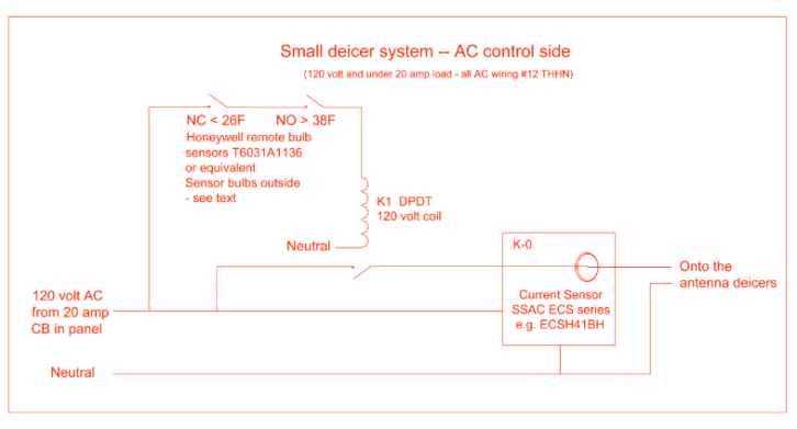
Automatic deicer controls vary in sophistication, with some even using exotic capacitor-based ice sensing schemes. You could use the VSWR sensor on the transmitter to activate the heaters. Or there is the pragmatic, reliable controller that my cohorts and I have used with great success (see schematic 1).
If your antenna is very high, it’s somewhat difficult on the ground to determine exactly what’s going on up there. However, atmospheric physics does provide one absolute: Near the earth, temperature only drops three degrees for every 1,000 feet AGL, so that is a definite value. Even on the tallest towers we know what the temperature should be around the antenna.
(Footnote: The lowest layer of the earth’s atmosphere is the troposphere, and its boundaries are described by the lapse rate, in this case the uniform decrease in temperature as we go higher. The troposphere extends from the surface to about 11 miles up and contains about 4/5 of the total volume of the gases that encircles the earth. At the point where the lapse rate becomes non-linear you have entered the stratosphere where they filmed “Zombies of the Stratosphere” with Leonard Nimoy.)
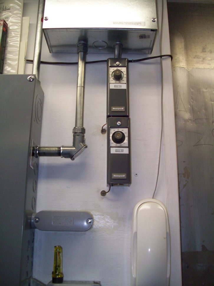
Because icing can only occur in a relatively narrow range of temperature — too far above freezing and you have rain, too far below freezing and you have snow — our automatic controller can make sensible decisions when to turn on and off the deicers. With this in mind, you will notice that the two series temperature sensors in the system diagram have set point of 38º F to close and 26º F to open.
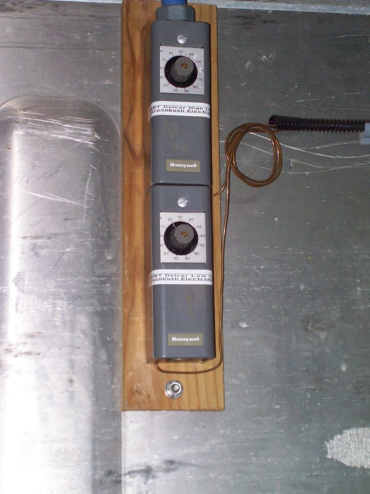
The antenna associated with this controller has a center of radiation 390 feet above ground level. These particular thermostat units are Honeywells with remote sensor bulbs, so the switches are inside and the bulbs are usually placed outside on the north side of the building (to avoid being tricked by solar heating) and away from heat sources. You can adjust the set points tighter or looser for temperatures that make sense for your tower height and experience. Setting the dead band around the selected action temperature for just a few degrees usually provides enough hysteresis to avoid control jittering.
Some 99.9% of the time, this control system in a simple manner will reliably anticipate any icing condition, reduce heater operation (cut the electric bill) and extend heater life.
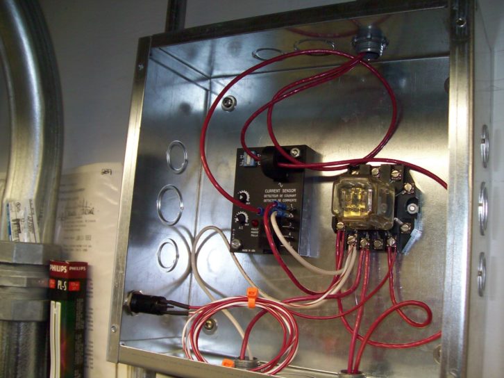
On the remote control side, the current sensor in conjunction with the auxiliary contacts on the AC power control relay provides three status outputs for the remote control (see schematic 2).
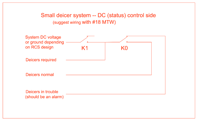
These are useful in avoiding having to drive out to the transmitter in icy, dangerous weather to find out what’s what. The three status conditions are:
The Deicers required status is operated by the closure of the auxiliary contacts on the deicer power relay, which supplies a voltage or a ground, whatever your remote control system needs. This voltage or ground is then connected to the current sense alarm relay and if the over-current NO contacts close, the Deicers normal status should come on. If the current is lower than the set point, the sense relay will drop out of alarm and make the Deicers in trouble contacts close, turning on this alarm condition.
On the power side, as I often mention when working with line level AC power: Be careful and never work alone. These are lethal voltages. If you are not completely comfortable working with AC power, bring in your usual electricians and let them do the AC while you have the fun on the DC side.
How to Set Up the Current Sensor Alarm
The heart of our status/alarm section is an SSAC current sensor. The wire carrying the current to the deicer(s) is passed through a small current transformer, and the voltage analog created is used to make either an over- or under-current alarm closing an onboard relay. For our purposes we will select the alarm on over-current.
To adjust, begin with the deicers consuming normal current, setting the alarm adjust pot just beyond the trip point when an over-current alarm appears such that the sensor will drop out of alarm when the current is low. Using this arrangement will provide an alarm to the remote control system when the current consumed drops below normal as well as on the odd occasion that the sensor has failed.
Occasionally, in a small antenna with modest heaters, the current consumed will be small and the pot for the alarm set point a little critical or at an extreme. In this case loop the wire that passes through the current sensing transformer two or three times to get the adjustment into the center of the pot’s range for better vernierity.
(This is a great word. The lexicon of engineering sometimes co-ops or creates a term known only to us. Vernierity means “adjustments in very small increments.” One definition of a vernier is a small auxiliary device used with a main device to obtain fine adjustment, such as those on a surveying transit or the turns counter on your FM transmitter final amplifier. The word honors French mathematician Pierre Vernier, who died in 1637.)


