There are several reasons that an FM station would participate in the build of a broadband antenna system, including:
• Construction of a new main transmitter site, where tower space is limited;
• Construction of a new auxiliary transmitter site, where space is limited;
• The desire to use a tower with limited capacity to hold additional antennas.
Of course there are many instances where the tower owner sees an advantage in providing a master antenna to accommodate all its FM clients. In this article we’re going to look at “broadband” antennas provided by some well-known manufacturers, along with some examples of their use. The use of a broadband antenna might very well solve a problem for you in the future, so please read on.
Mt. Ascutney
Shively Labs recently constructed a semi-custom broadband antenna for VPR’s Mount Ascutney site near Windsor, Vt. I spoke with Sean Edwards, RF designer and project lead, about the system.
“The unique requirement of this system is that there were two tenant stations that needed to be omnidirectional, while the third needed to be directional — with a pretty significant null towards the northeast,” said Edwards.
The solution ended up being use of a six-element Shively 6014 panel antenna with modifications to its feed system — specifically, the type of feed and the power distributions. The antenna is a three-sided array, with two levels.
Each 6014 element is a crossed dipole, and each of those dipoles is fed by 3 dB hybrid. “If there is sufficient isolation between the dipoles, you can feed the reject load port as a second input,” Edwards said. The signals fed into the hybrid using the “normal” inputs radiate with right-hand circularity; the signal fed in to the “reject” port radiates in left-hand circularity.
Then the problem becomes fairly simple. “The stations that are nondirectional are fed in to each element at equal power,” he said. “The station that needs to be directional is fed at full power on two [of the three] faces, and at –10 dB [in this particular case] on the third.
“In that fashion, you’re able to produce both types of patterns in one antenna system.”
I asked Edwards about the power dividers used in the system (a diagram of which is seen as Fig. 1). The stations that are omni are all fed by way of the equal six-way power divider and equal-length cables. “We repurposed a –10 dB coupler [commonly used early on in HD Radio implementations] and modified it to become the –13 dB coupler,” he said. “The output from the –13 dB port went to a two-way power divider, and the ‘through’ port was fed into a four-way power divider. The resulting power delta is –10 dB. There are other ways to do it, but that’s how we approached it.”

The Shively 6014 panel antenna is made for broadband applications and has the capacity to handle 15 kW per element. Its VSWR specification for the entire 20 MHz of the FM band is 1.15:1 or better. The Mount Ascutney antenna accommodates stations on 88.1 MHz (WNCH), 89.5 MHz (WVPR) and 106.1 MHz (WHDQ).
Elements
John Schadler is vice president of engineering for Dielectric. He said the company makes two styles of broadband antennas for the FM band.
“First is the side-mount ring style, which would use our DCR-M elements, in the lowest power version. The next step up in terms of power would make use of the DCR-S elements, followed by the highest power version, which would use the Dielectric DCR-U elements. That antenna is capable of handling eight full-power stations.”
Antennas based on the Dielectric DCR-M or DCR-S elements are limited to 12 MHz of bandwidth; the DCR-U accommodates the entire 20 MHz of the FM band. The VSWR spec is 1.15:1 across the entire band.
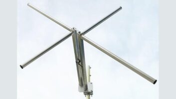
Dielectric also offers the FMVee, which consists of three circularly polarized stainless steel radiators mounted around on a structural mast, producing an omnidirectional pattern with than ±2 dB variance in the horizontal plane (for top-mount configurations). The design of the FMVee antenna offers control of the elevation pattern by adjusting beam tilt and null fill. This antenna type also offers 20 MHz of bandwidth and can handle 10 Class C stations.
Dielectric recently provided a DCR-U-based broadband antenna to Tall Tower Ventures in Miami, and accommodates six stations ranging from 93.1 MHz to 106.7 MHz.
“In terms of its physical size, the DCR-U is very aperture-efficient. It’s 38 inches in diameter,” said Schadler. “The amount of bandwidth you can get out of an antenna is directly related to the volume. It pushes its limits as far as the volume goes.”


Mt. Morrison
Recently, ERI worked with tower site owner Bear Creek Development in the design and construction of two combined antennas, both installed at Mt. Morrison near the Red Rocks Amphitheater west of Denver.
The first of the two antennas (model 1182-6CP-DA-SP) was designed to accommodate five Denver stations: KUVO, at 89.3 MHz; KYGO at 98.5 MHz; KIMN at 100.3 MHz; KOSI MHz at 101.1; and KXKL at 105.1 MHz. The number of stations that can share the antenna is really only limited by its power handling capability: This antenna is designed to handle up to 125 kW of combined power and has a single 6-1/8-inch, 50 ohm, EIA flanged input.
“A system like this is designed to handle the entire FM band and generally has a VSWR specification of 1.25:1, maximum, 88.1 MHz to 107.9 MHz,” said Bill Harland, the vice president of marketing for ERI.
He added, “Directional antennas are generally more challenging with respect to return loss performance. With field tuning the return loss is optimized with a target of a VSWR of 1.15:1 or better for the frequencies of interest.”
“The [north] antenna has a carefully design elevation pattern which minimizes RFR levels immediately below the antenna, as it is very close to the ground,” said Harland. The area surrounding the site is fenced.
The Mt. Morrison south antenna (model 1051-2CP-DA-SP) was also designed and built by ERI and located not far from the north antenna. It serves as an auxiliary site for two of Entercom’s Denver stations: KQMT at 99.5 MHz and KQKS at 107.5 MHz.
Since neither of these stations is within 800 kHz of any of the “north” antenna stations, I asked Harland why they didn’t just share one antenna after all.
“The azimuth pattern of the 1051-2CP-DA is much narrower than the directional antenna for the north site,” he wrote. “The KQMT main antenna is directional from Lookout Mountain and the directional antenna designed for the south site allowed this auxiliary facility to be licensed at higher power.”
The south antenna is a “single curtain” directional FM antenna has a special feed system to handle the nearly 30 kW combined analog and digital power of the stations using its two-element array. The site elevation is more than 7,800 feet. “The system is optimized and field tuned for the two frequencies and the measured VSWR for each channel is substantially better than 1.10:1,” Harland said.
The use of wideband antennas (fed by the output of a combiner) is common practice making use of the evolution in antenna technology that has occurred for VHF FM, especially over the last 50 years. As the FM service gained popularity in the late 1970s, many companies invested in their FM licenses and moved them to better locations, such as Mt. Wilson (taking Los Angeles as an example), often times buying land and putting up their own building and tower. As the service matured and became more valuable, more combined antennas came in to use (a perfect example of which is the 16-station system on top of the Empire State Building). There are many good reasons for using combined antenna systems, as we have seen in this article. Keep this technology in mind as you work on your own site designs in the future.
Doug Irwin, CPBE AMD DRB, is vice president of engineering at iHeartMedia in Los Angeles and a technical advisor to Radio World.