Lightning protection is a critical aspect of establishments that operate sensitive electrical equipment, especially in the broadcast industry. Tied to this first line of protection against lightning and voltage surge is the grounding system. Unless it is designed and installed properly, no amount of surge protection will work.
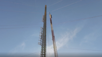
One of our TV transmitter sites sits on top of a 900-foot hill known for experiencing lightning surges. I recently got assigned to manage all our transmitter sites; the problem, therefore, was passed on to me.

A lightning event in 2015 knocked out the power, and the generator did not stop running for two days. On inspection, I found out that the utility transformer fuses had blown up. I also noticed that the newly installed automatic transfer switch (ATS) LCD display was blank. The security cameras were damaged and the video program feed from the microwave link was blank.
Worse, when the utility power was restored, the ATS blew up. To get us back on the air, I was forced to switch the ATS manually. Estimate of the damage was more than $5,000.
Mysteriously, the LEA three-phase 480V surge protector showed no indication of working at all. This intrigued me because it was supposed to protect all the equipment in the site from such an event. Thankfully, the transmitter was fine.
I started investigating right away and my first instinct was to check the grounding system.
There was no documentation of the ground system installation, so I had no way of finding out about the system or the ground rods. As you can see from Fig. 1, the soil is very thin at the site, and the rest of the ground underneath consists of Novaculite rocks, which are like a silica-based insulator. With this kind of terrain, the usual ground rods will not work, and I needed to determine if they installed a chemical ground rod and if it was still within its useful lifespan.
GROUND RESISTANCE MEASUREMENT
There are plenty of resources on the internet about ground resistance measurements. For making these measurements, I chose the Fluke 1625 earth resistance meter, seen in Fig. 2. It is a versatile device and can do ground measurements with either the ground rod only or with the ground rod connected to the system. Added to that are the application notes that one can easily follow in order to have an accurate result. This is an expensive meter so we rented one for the job.
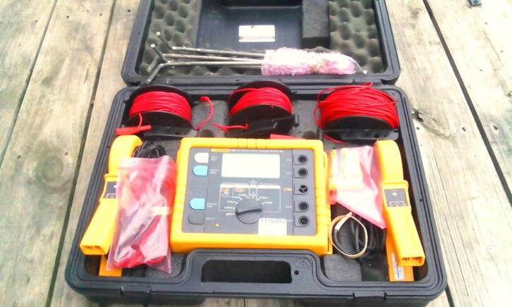
Broadcast engineers are used to measuring resistance of, say, a resistor, only once and we get the actual value. Ground resistance is different. What we are looking for is the resistance the surrounding ground will offer in the event that a surge current passes through.
I used the “fall-of-potential” method in measuring the resistance, and the theory is explained in Figs. 3 through 5.
In Fig. 3, there is a ground rod E with a given depth and a stake C some distance away from the ground rod E. A voltage source VS is connected between the two, and this will generate current between the stake C and the rod E. With a voltmeter, we can measure a voltage VM between the two. The closer we get to E, the lower the voltage VM becomes. VM is zero at ground rod E.
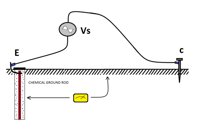
On the other hand, as we measure the voltage closer to the stake C, VM goes higher. At stake C, VM is equal to the voltage source VS. Following Ohm’s Law, we can have the ground resistance of the surrounding dirt using the voltage VM and the current induced by VS at stake C.
Let’s say for the sake of discussion that the distance between the ground rod E and the stake C is 100 feet and the voltage is measured every 10 feet starting from the ground rod E towards the stake C. If the results are plotted, the resistance curve should look something like in Fig. 4.
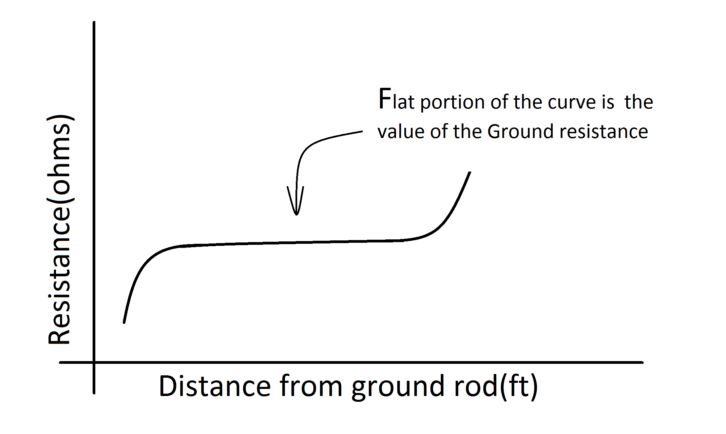
The flattest part is the value of the ground resistance, and this is the extent of the influence of the ground rod. Beyond that is part of the vast earth, where the surge current will not penetrate anymore. This is understandable considering the impedance goes higher and higher at that point.
If the ground rod is 8 feet long, the distance of the stake C is usually set at 100 feet and the flat part of the curve is around 62 feet. There are more technical details that cannot be covered here, but they can be found in the same application note from Fluke Corp.
The setup using the Fluke 1625 looks something like that in Fig. 5. The 1625 Earth Resistance Meter has its own voltage generator, and the resistance value can be read directly from the meter; there is no need to calculate the ohms value.
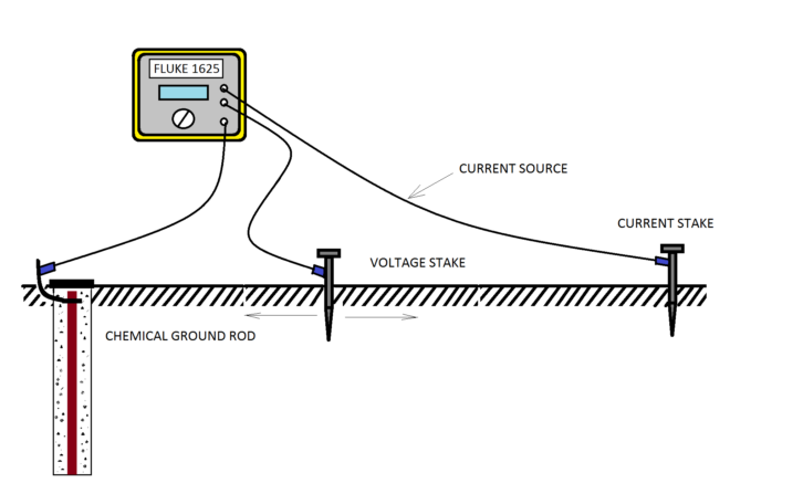
The reading is the easy part while the hard part is driving the voltage stakes. For accurate readings, the ground rod is disconnected from the ground system. For safety, we made sure there was no lightning or possibility of a fault when it was done because the whole system was floating from ground during the measurements.
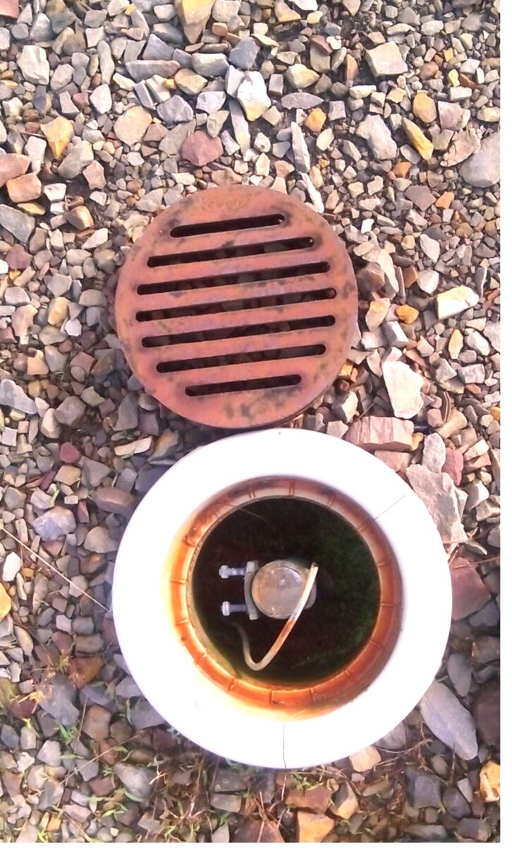
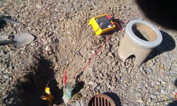
After looking around, I found the ground rod (Fig. 6), and indeed it was a chemical ground rod made by Lyncole Systems. The ground rod consists of an 8-inch diameter, 10-foot hole filled with a special mix of clay called Lynconite.
In the middle of this hole is a 2-inch diameter hollow copper pipe of the same length. The mixed Lynconite yields a very low resistance for the ground rod. I was told that during the installation of this rod, dynamite was used to make the hole.
Once the voltage and current stakes were planted in the ground, a wire was connected from each stake in turn to the meter, where the resistance value was read.
I got a value of 7 ohms ground resistance, and this is a good value. The National Electrical Code requires that the ground electrode be 25 ohms or less. The telecommunications industry generally requires 5 ohms or less because of the sensitive nature of the equipment. Other big industrial plants require even lower ground resistance.
As a practice, I always ask those who have more experienced doing this kind of work for advice and insights. I asked Fluke Tech Support about the disparity in some of the readings I got. They said that the stake at some point might not have made a good contact (possibly because of harder rock) on the ground.
On the other hand, Lyncole Ground Systems, maker of the ground rod, said that most of the readings were low. They were expecting higher readings. However, as I read articles on ground rods, disparities like this happen. One study where they made measurements each year for 10 years found out that 13–40 percent of their readings were different from the rest. They also used the same ground rod that we use. It thus matters that multiple readings are done.
I got one other electrical contractor to install a more robust ground wire connection from the building to the ground rod to prevent copper theft in the future. They also did another ground resistance measurement. However, it rained a few days before they made the reading and they got an even lower value than 7 ohms (I did the reading when it was very dry). From these results, I believe that the ground rod is still in good shape.
SOME CHANGES
I moved the 480V surge suppressor to a point in the circuit right after the service entrance, immediately adjacent to the main disconnect switch. It used to be in a corner inside the building. This new location puts the surge suppressor first in line whenever there is a lightning surge. Second, it is at the shortest possible distance from the ground rod. In the previous arrangement, the ATS was in front of everything, and it always got the first hit. The three-phase wires to the surge suppressors and its ground connection were made much shorter to reduce impedance.
I again went back to investigate the strange problem of why the surge suppressor did not work while the ATS blew up during that lightning surge. This time, I thoroughly checked all the ground and neutral connections of all the circuit breaker panel board, the back-up generator and the transmitter.
What I found was that the ground connection of the main breaker panel was missing! This was also where the surge suppressor and the ATS get their ground connection (and consequently, the reason why the surge suppressor did not work).
The reason it was missing is that sometime before the ATS was installed, copper thieves cut the connection to this panel. Previous engineers fixed all the ground wires back, but they were not able to restore the ground connection to this breaker panel. The cut wire was not easy to see because it was at the back of the panel. I fixed this connection and made it more secure.
A new three-phase 480V ATS was installed, and three ferrite toroidal cores from Nautel were used at the three-phase input of the ATS for added protection. I made sure that the surge suppressor counter was working as well so that we will know whenever there is a surge event.
When the storm season arrived, everything went humming along well and the ATS worked perfectly. However, the pole transformer fuses were still blowing up, but this time the ATS and all the other equipment in the building were no longer affected by the surge.
We requested the electric utility company to check out the blowing fuses. I was told that the site is at the end of the three-phase transmission line service and thus more prone to surge issues. They cleaned up the pole and installed some new devices on top of the pole transformers (I believe they are some sort of surge suppressors as well), and that did stop the fuses from blowing up. I am not aware if they did something else on the transmission line, but whatever they did, it worked.
All this happened in 2015, and since then we haven’t had any problem related to voltage surges or lightning storms.
Resolving voltage surge issues is sometimes not easy, and one has to be careful and thorough to make sure everything is accounted for in terms of wiring and connection. The theories behind grounding systems and lightning surges are worth studying. Single-point grounding, voltage gradient and ground potential rise during a fault among other issues must be well understood so that the right decisions are made in the installation process.

