At the end of the pipe in every FM station operating in stereo — which probably is 99.5% of the over 7,000 FM outlets operating here in the United States — the delivery package to be transmitted is of a composite construction.
Our standardized stereo transmitted format, originally approved in April 1961, has been very durable and, in more recent times, digital HD Radio capability has been integrated successfully into this stereo system to ride along on a compatible basis.
The information elements ordinarily contained in the classic composite package are:
- A monophonic baseband, an equal blend of the original left and right
- A 19 kHz “pilot” sine wave that is utilized in the stereo demodulation process
- An amplitude-modulated envelope centered on 38 kHz that contains the “difference” information used in the demodulation process
- Various additional FM modulated subcarriers with an abundance of uses such as secondary general broadcast (think “data”) and for station purposes (e.g. remote control telemetry and audio backhaul). We should also include in this grouping the more recent addition of the digital data stream at 57 kHz (three times the pilot frequency of 19 kHz), a.k.a. “RDS.”
HD Radio, because of its digital and bisymmetrical offset RF carrier construction, is normally integrated into the signal package at the transmitter.
The package
Many if not most of the non-HD stations deliver their composite stereo “package” from the studio via an STL in a signal-ready form for direct plug-in into the FM exciter.
Not only is the composite demodulation described in this article useful as a confidence check and troubleshooting aid, but in the age of FM translators for struggling AMs, the convenience of having discrete left and right at the transmitter site facilitates separate processing for the mono AM and stereo FM translator.
Covered here is the “Honduran economy model” composite demodulator, which only provides discrete left and right adjustable to near +10 dBm when terminated into 600 ohms and a confidence LED showing the presence of the 19 kHz pilot which also indicates that the unit is demodulating stereo.
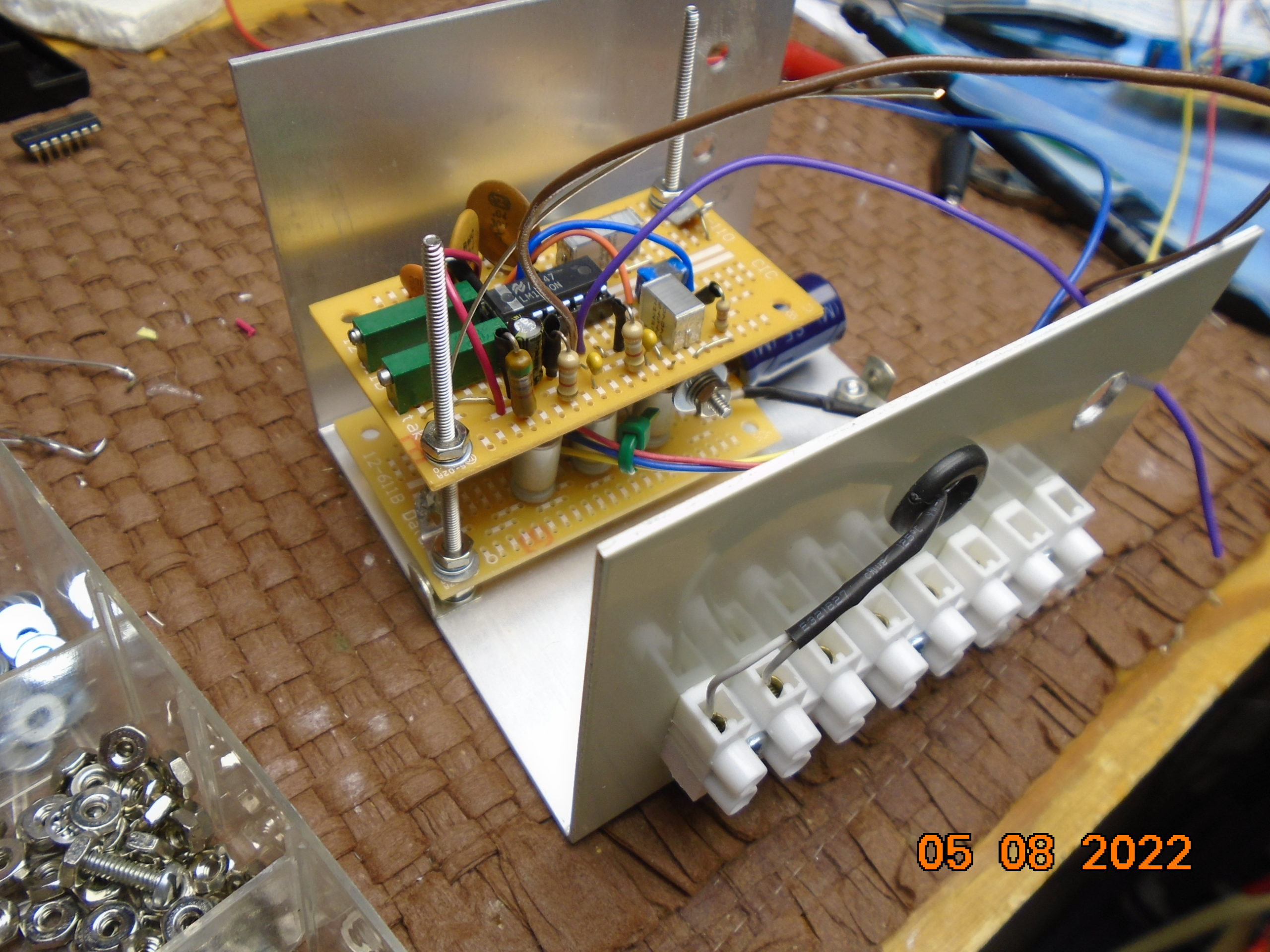
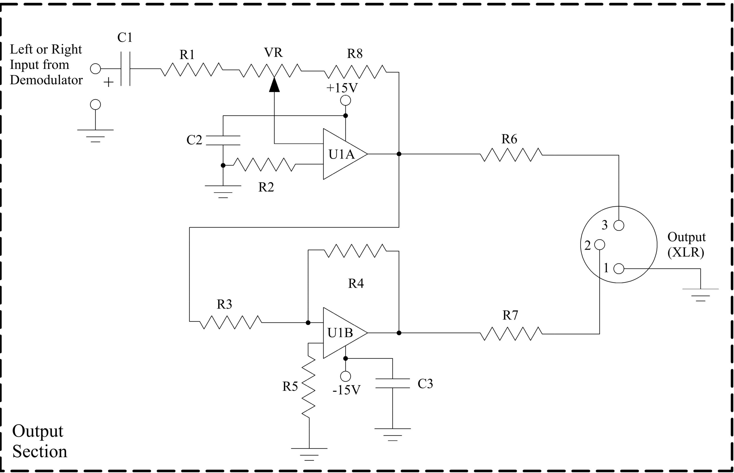
We built the pictured unit in discrete form, hand-wired on three PCB protoboards not only as an alpha model to prove our concept but also to demonstrate that with patience, you can make and customize your very own version. See the schematic diagrams.
This design is suitable for a finished printed circuit board. Features that can be added include a fully adjustable separate mono output with selectable 8 kHz roll-off to assist in NRSC compliance, a separate stereo headset amp with jack to help in high-noise environments, a 12-segment LED “VU” meter and an RDS confidence light that illuminates when the 57 kHz signal is present at approximately 2% of the modulated envelope.
Details, details
Our motivation for using the classis LM-1800 is its unfussy, non-critical, no unique coil or transformer concept. With typical >40 dB left and right separation and workable rejection of any SCAs present, the LM-1800 is more than adequate for the task.
On a practical note there are only four adjustments, and since these four are fundamentally needed one time only, we put them inside. For easy “reach-ability,” the composite input level and pilot capture potentiometers (located on the middle PCB) are right-angle types and face an open side of the base shell of our mini-cabinet. The left and right level adjust pots controlling the audio level adjusts face up since they’re on the top.
We’ve segregated the functions of power supply, demodulator and output onto separate PCBs. As mentioned, this allowed us to assemble, test and modify each independent section as we went.
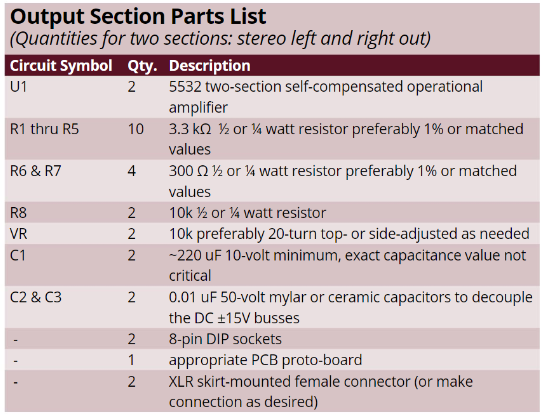
Regular Radio World readers will readily recognize both the power supply concept and the output section as a variation of the circuits that were used in our unbalanced-to-balanced adapter project in 2020.
The European-style terminal strip for the wall wart AC power in and left/right out was per the request of the user in Juticalpa, Honduras. The composite BNC input matched the output(s) on the STL receiver.
Tuning it up
Adjustment? Nothing fancy or tricky here. Refer to the demodulator section of the schematics.
Input 19 kHz at 0.35 volts or so peak-to-peak on the composite input connector and then adjusting VR2 to set level at pin 1 on the LM1800 to about 80 mV p-p.
[An aside: This adjustment procedure assumes that the input will be the industry standard 3.5 volts peak to peak composite envelope. The LM-1800 flysheet indicates that their testing was optimized at an 800 mv PtoP level at pin 1 and with the author’s procedure, this should set the input to this ideal level point. The manufacturer’s flysheet (see parts list) on this LM-1800 chip is full of additional interesting details. Well worth the read. The 1977 National Semiconductor Audio Handbook is another great source of related concepts and ideas. See section 3 page 23.]
Proceeding on, then adjust VR1 to land the oscillator in the center of its 19 kHz capture range while looking at Pin 11 on a scope. The pilot present indicator should come on during this adjustment process.
We put a little connection loop on the PCB attached to this Pin 11. This made the scope connection for this test point easy and convenient.
On my bench, I’m lucky enough to have a classic Orban 8000, and sending through separate left and right at identical levels allowed me to adjust the demodulator outputs to match. A null test confirmed that my balance was very nearly right on.
At this point, using either a stereo headset or studio-grade monitor, you should assess the audio quality. Your golden ears will indicate whether you need a little more level to lower the noise and to achieve better separation by turning up VR2 slightly.
An actual THD measurement with a crude roll-off filter was very low, coming in under 2%. Keep in mind that most of that 2% is just noise above 15 kHz and in the audible spectrum probably is closer to the 0.8% that the manufacturer touts.
The 20-turn pots used on the left/right level adjusts (VR in the output section) have considerable range and vernierity. If you love to tweak, you’ll love playing with this unit.
By the way, we couldn’t find an AC 15 volt or higher wall wart in our redundant and harvested wall wart box, so we made one using the case of an old wall wart recharger for a long-gone cordless screwdriver. We took out the insufficient low-voltage transformer and replaced that with a new, compact 5-watt 24 volt AC control transformer originally provided for a furnace humidifier but not needed.
Now your turn has come to make your very own composite demodulator to suit your unique needs and station demands.