If you’re like me, a little project that’s mostly for fun can also serve as stress therapy. This one is actually useful too! It’s a classic sound effects button box using modern technology.
The heart of the button box is the Adafruit Audio FX Sound Board. They’re sold on Amazon and other online retailers.
For this application, choose either the board with built-in amplifier that allows “cue” speakers, or just the basic board that provides only a line out.
There are two options: One supports eight sound effect buttons, the other allows 11. (Notice one board has pins 0–7 while the other has pins 0–10.) For applications where sound effects are only a few seconds each, the on-board memory is sufficient.
If you have basic tools, a USB cable and soldering skills, the rest is easy.
The board has a micro-USB connector, which means the power and programming connections are all complete in one common plug. When the USB line is connected to the computer, the Adafruit acts like an external drive; when the USB is connected to a power block, the Adafruit acts like a button box. The only other external connection will be the audio line out cable, which depends on the user’s connection needs.
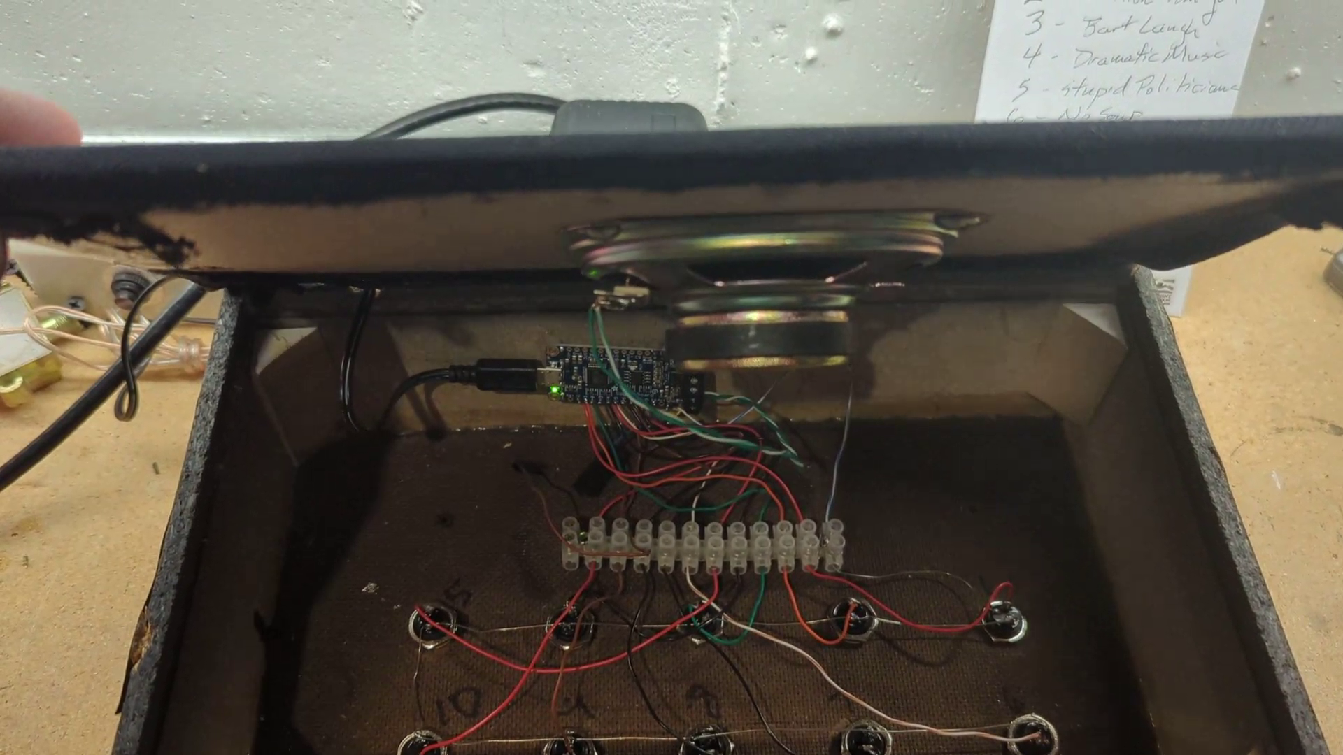
For this project, it is easy to use any small speaker enclosure that can be opened by prying off the front face. The front face and speaker will become the back of the button box (see Fig. 1). The pushbutton switches are mounted into the back of the speaker box, which becomes the front (Fig. 2).
Internal wiring
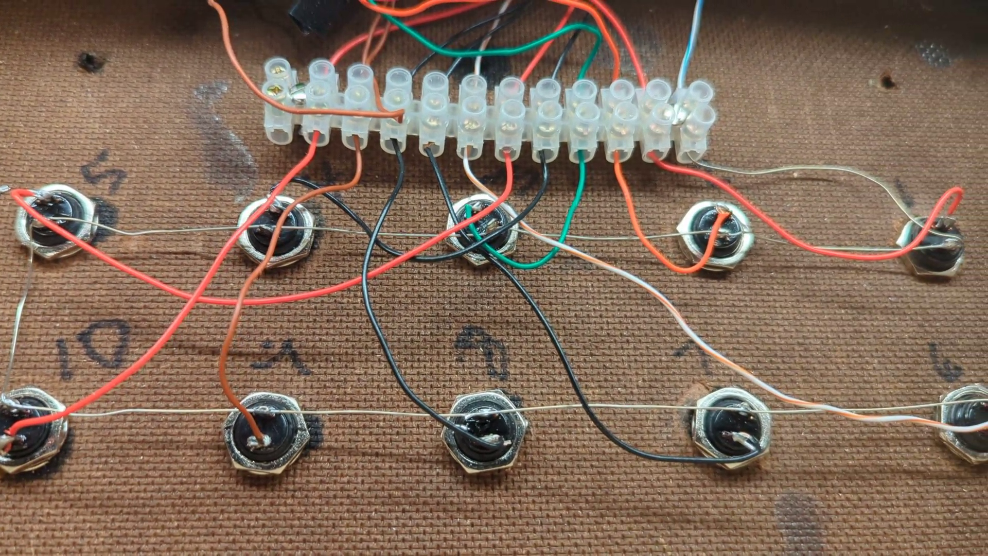
A sound effect is triggered when the pin number of the hole on the Adafruit board is grounded. For example, the audio file stored in position zero will play when the wire soldered into hole zero is momentarily connected to ground. The way this is accomplished is that the momentary pushbutton switch for playing audio file zero will have one pin wired to hole zero on the sound board and one pin soldered to ground. The same process applies to all the switches … hole one tied to switch one, etc. and the other side of all the switches tied to ground. (This project used a terminal strip between the switches and the Adafruit Board).
Fig. 3 shows all the connections on the Adafruit board. The switch connections are shown across the bottom on holes 0 to 10, and also the ground connector (the ground wire common to all switches).
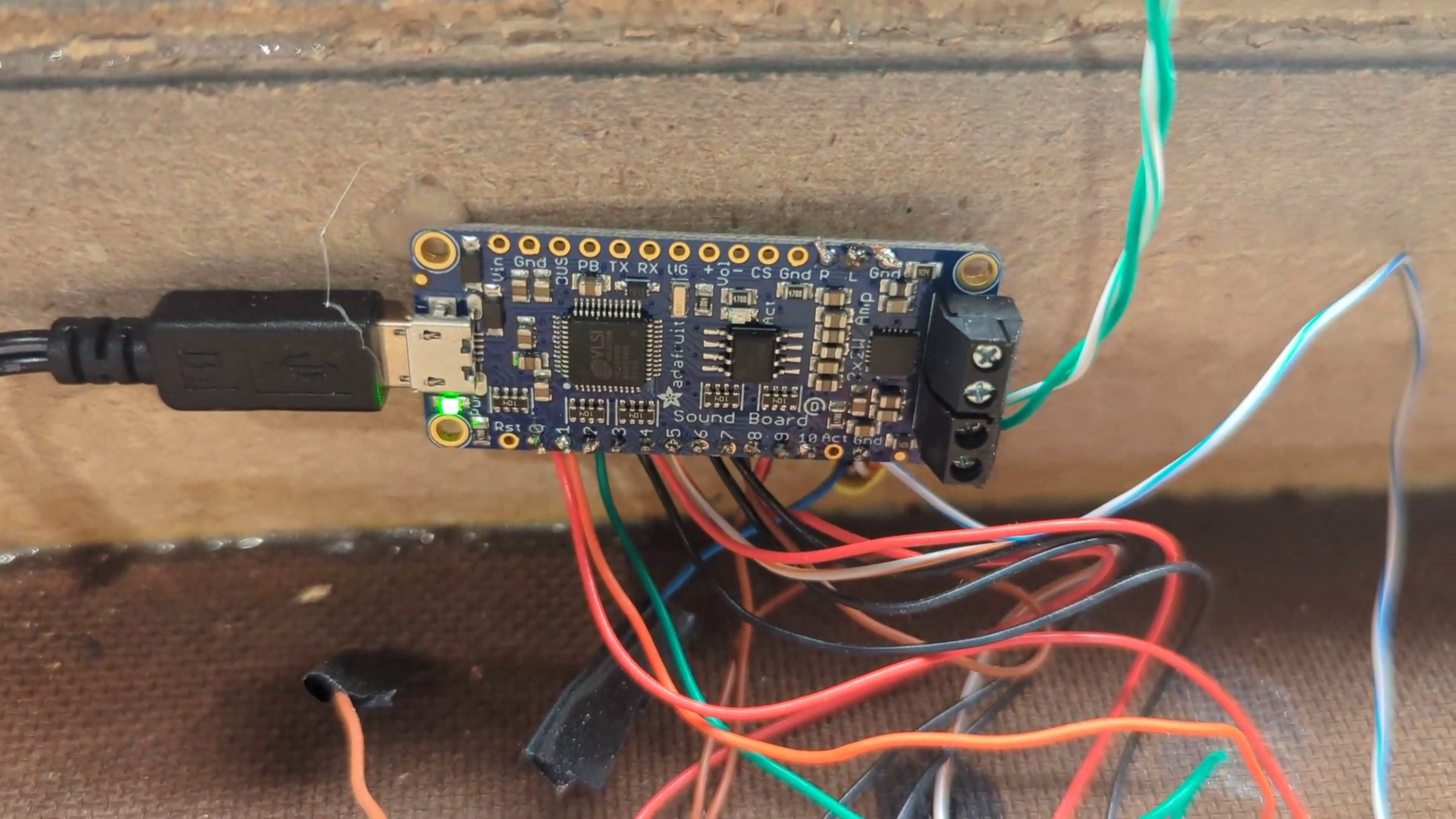
The top of the Adafruit board has the line out connections: left, right and ground. The end of this board has the left and right speaker connections. Only one speaker is connected in the photo. Obviously, this board can be used in many other applications with other interconnections.
There is usually a test audio file that will play when button zero is pushed (hole zero is grounded momentarily). It is very short, but it’s a good way to test connections prior to loading audio into the unit.
[Subscribe to Radio World Engineering Extra]
Loading the audio files
Loading up the Adafruit with sound files requires a few simple steps: resaving the files as .ogg files; renaming the files to fit the format for the Adafruit board; and dragging the files into the Adafruit folder.
Step 1: Locate the audio files to be loaded into the button box and place them on a computer. The files will need to be converted into .ogg files. This can be done at no cost through various online or downloadable programs. One app in common use in radio stations that can do this is Audacity (www.audacityteam.org/download/). Open Audacity and drag one of the sound files into the Audacity workspace. Once opened, use the process File | Export | Export as Ogg. The file will be saved under the original file name with a different icon and the .ogg suffix. Convert all of the files to be used in the button box.
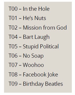
Step 2: Rename the .ogg files for the button box. This is a simple process. If there are 11 sound effects to go to 11 buttons, they must be renamed as T00, T01, T02 through T10 before they can be loaded into the Adafruit board. Decide which effects go to which button and rename them accordingly (see Fig. 4).
Step 3. Connect the Adafruit board to the computer through the USB cable. It should behave like any USB drive. The workspace may show the test file, usually listed as “T00 Left/Right.” Delete file T00 and drag in the files that are renamed in Step 2 above. The buttons should now be active and play the audio files as configured.
Wrap it up
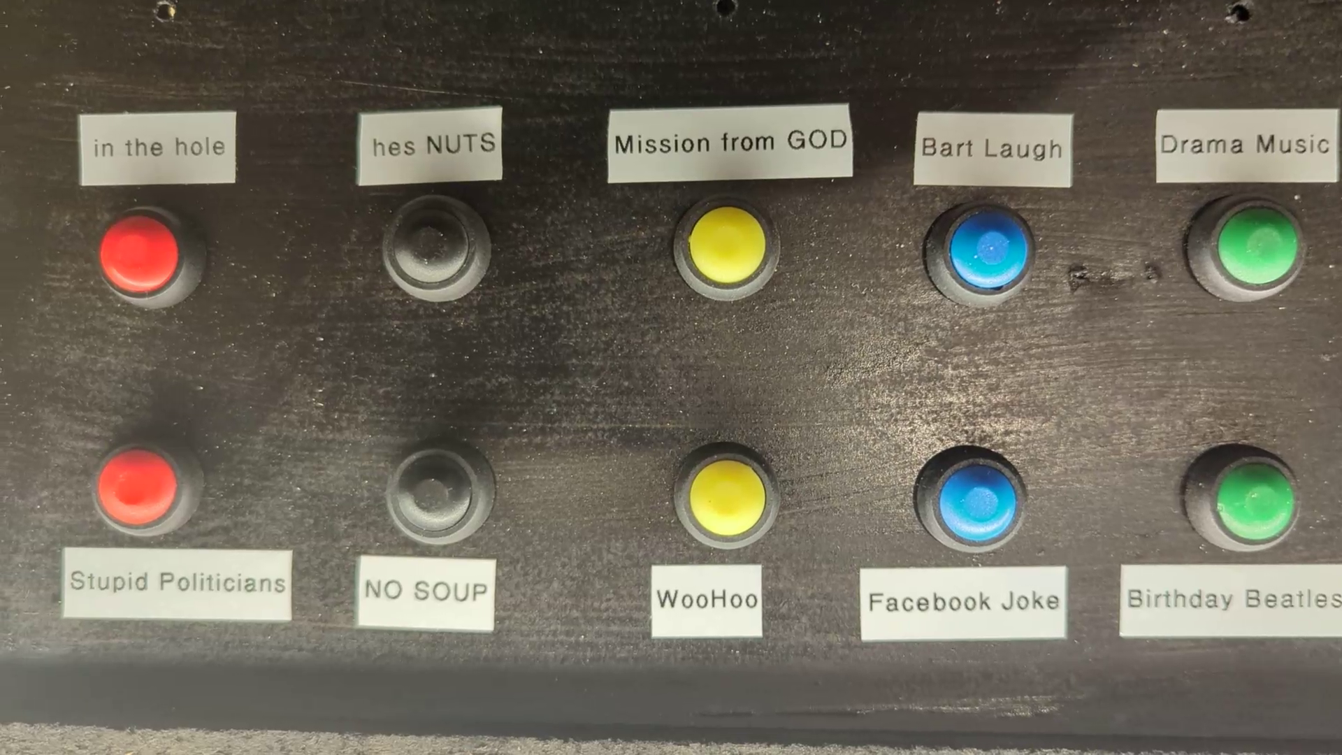
There is some planning required to decide where to drill a hole in the box to run the wires, possibly painting the back of the box, and how to lay out the switches (Fig. 5). Use colored pushbuttons if you wish, and affix labels to identify the various cuts.
With just a few dollars in parts and whatever old speaker or other enclosure you have lying around, you can make a sound effects button box that will liven up the morning zoo or other live show. It, and you, will be a big hit with the air staff!
The author is a semi-retired independent engineer in southern Colorado. He enjoys supporting small radio operations.
RW welcomes your Tech Tips, email us at [email protected].