Establishing and keeping to a standard audio level, especially in studios, has been a problem since the first radio station went on the air.
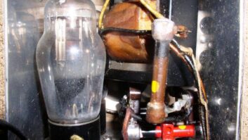
Back in the 1960s, audio console output levels were usually +8 dBm (eight decibels above one milliwatt into 600 ohms) for tube and early solid-state consoles.
That +8 was a compromise between headroom and noise. A 1969 vintage Gates Statesman audio console had 74 dB of dynamic range between peak clipping at +18 dBm and the noise level. That makes 64 dB between normal program level and noise. It was fine for AM stations, where a signal-to-noise ratio of only 45 dB was FCC-required between 100% modulation and no audio.
Then came FM with an FCC-required 60 dB or better signal-to-noise ratio in the entire audio chain. The Statesman’s 64 dB signal-to-noise left only 4 dB for additional noise in the station audio before it could not make FCC specs.
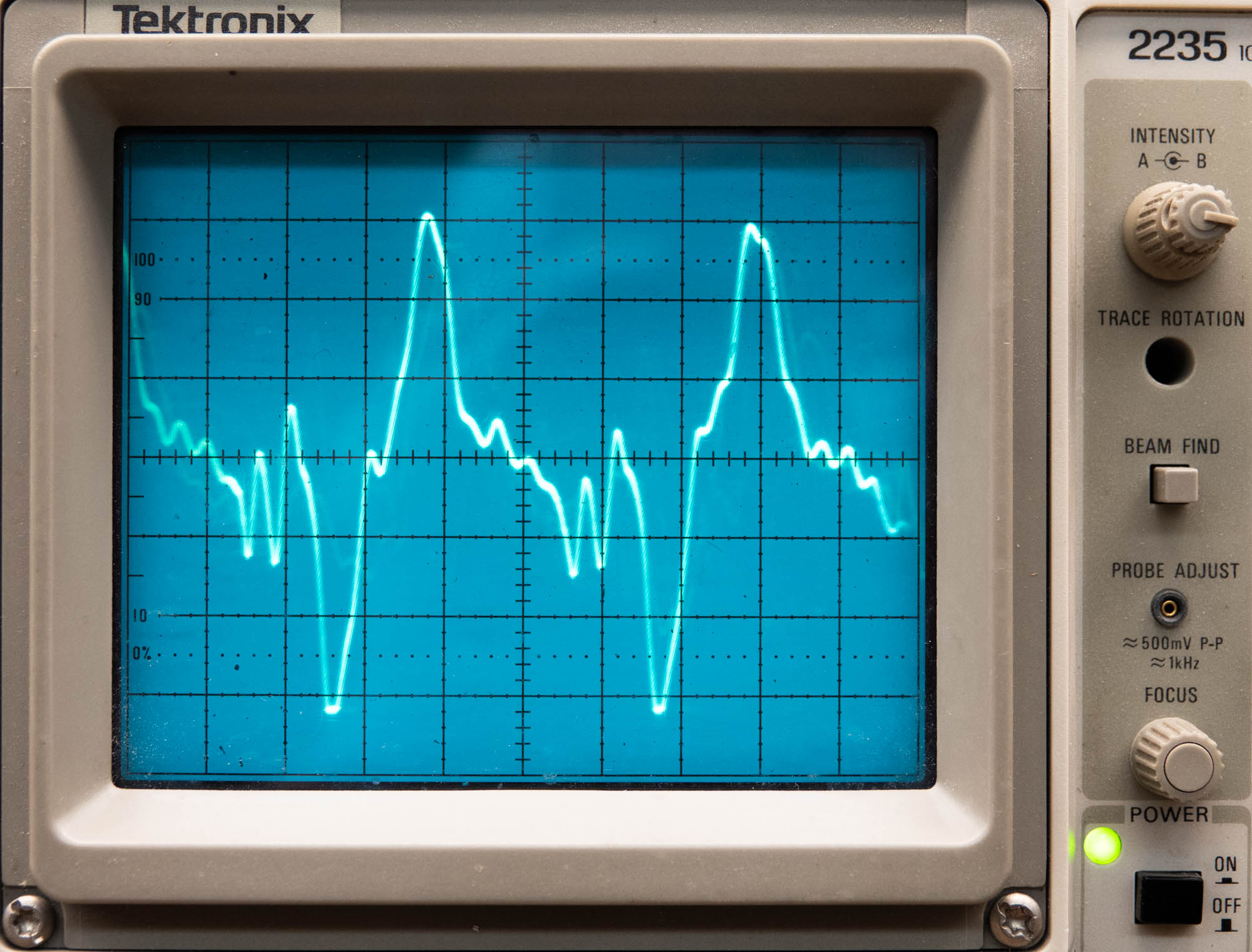
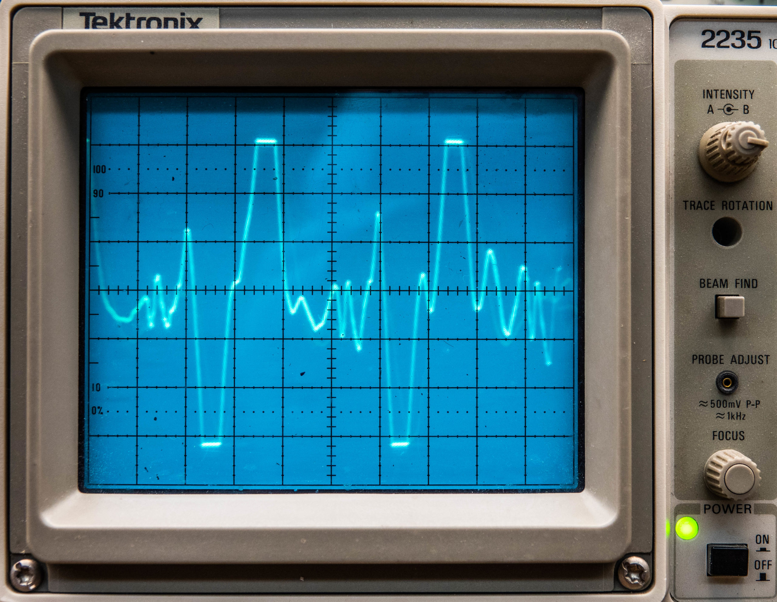
Fig. 1 shows an oscilloscope view of a normal voice, where there is just enough dynamic range to accommodate it. Vertical peaks are just at the equipment limits. I prefer an oscilloscope to see exactly when peak clipping occurs. There is a discussion of this in a Nov. 9, 2016, article I wrote in Radio World, “Calibrate Analog Audio Consoles.”
If you are following the numbers, you will realize there was only 10 dB between 100% (0 dB on the meter as seen in Fig. 2) and audio clipping. The same microphone and voice sounded different from one audio console to another depending on the voice and the operator running the controls.
My testing of audio, with an oscilloscope 50 years ago, showed that some voices can have as much as a 16 dB average to peak ratio. From that I deduced that ALL audio consoles need their analog VU meters calibrated to show 100% when peak clipping occurs 20 dB higher. The extra 4 dB takes care of audio when operators let levels run hot.
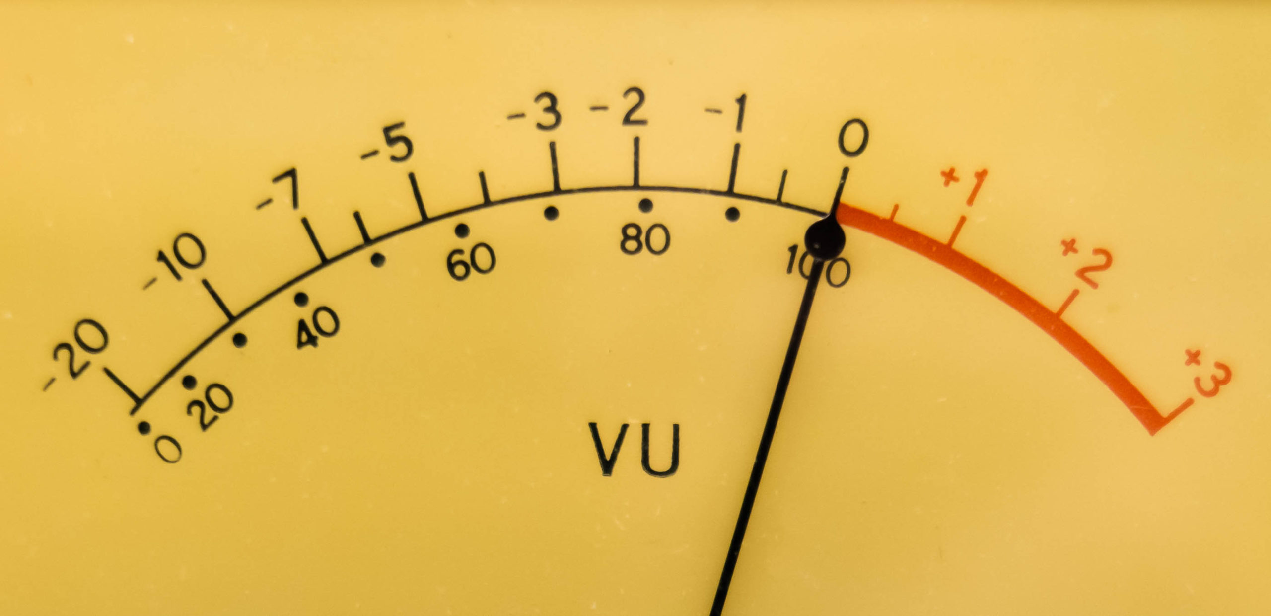
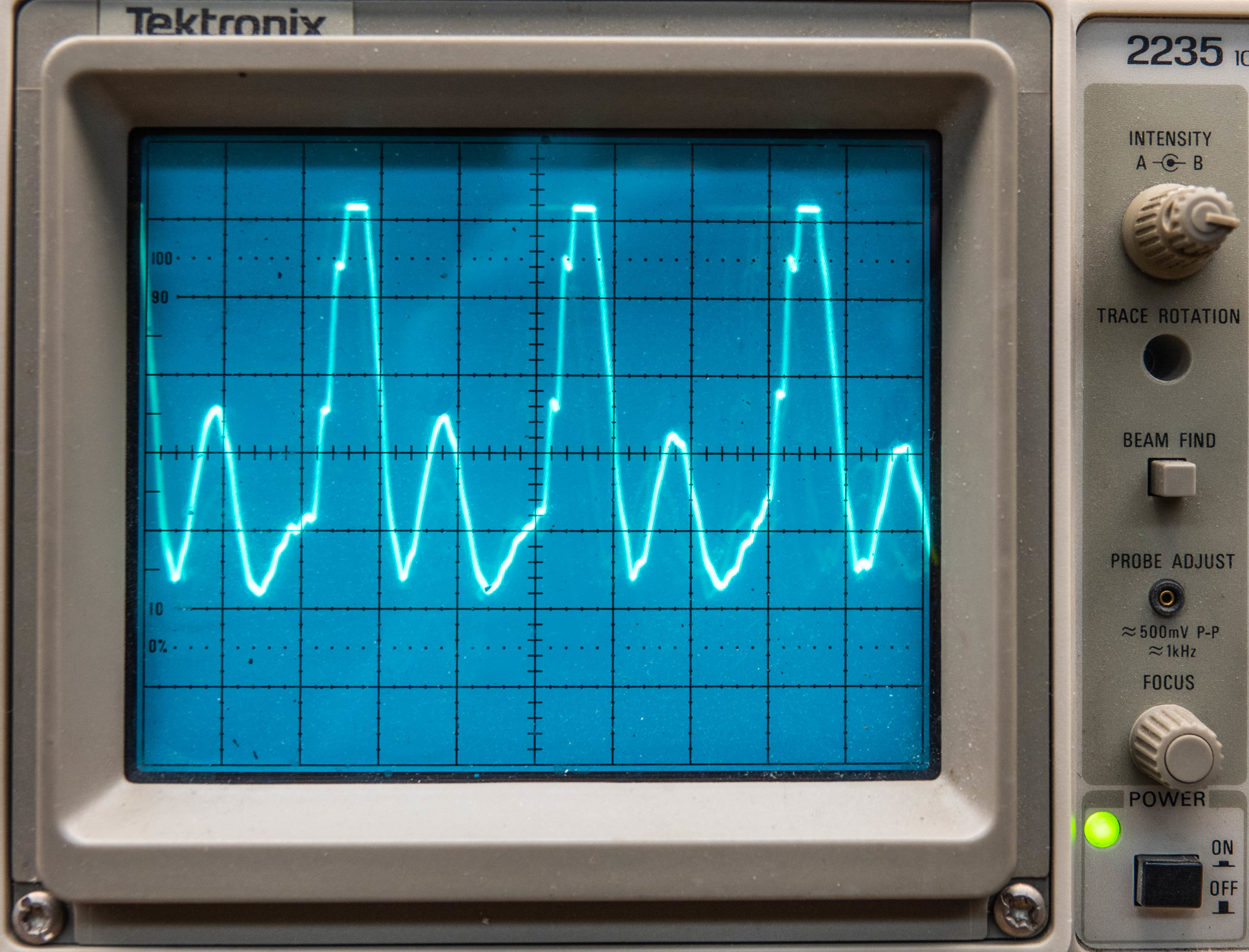
Fig. 3 shows audio driven into peak distortion. Not all people hear peak clipping distortion, that grungy and tearing sound added to the original content. Women listeners are the first to tune out. Ouch!
[Read More Articles by Mark Persons]
Recalibrating a meter to fix that on an older console meant maybe –2 dBm output level when the VU meter said 100%. The signal-to-noise ratio would then be degraded by 10 dB. Those with good ears would say the audio was not distorted, but there was hiss in the background. Which one is more acceptable?
Hi-Fi home stereo systems were gaining popularity in the 1960s and had better audio fidelity than what broadcasters could provide. No wonder there was a push to design and build better audio consoles, especially for classical stations. For rock and roll listeners of the day, distortion and hiss hardly mattered because the sound was just loud!
Audio quality improved when integrated circuits such as the NE5532N hit the market. These and similar operational amplifier chips make it possible to send and receive balanced audio without the need for transformers.
As you probably know, even the best transformers color the sound of audio a bit. While that coloration may be desirable and sought after in some recording studio settings, the goal is generally to keep a broadcast air chain as clean as possible. Doing without transformers solved that problem.
ICs can deliver about +24 dBm. The specified normal output level on most consoles, using this technology, is +4 dBm, which yields 20 dB of headroom. Typical examples are the Radio Systems RS-12A and Arrakis 150 through 12,000 series audio consoles. That 20 dB is necessary to help protect from peak clipping when operators like to hear mechanical VU meter needles “click” as they drive the audio hard and the needles into the peg. There is still 80 dB or more between normal program level and the noise floor. We’ve come a long way!
Devil and details
Audio processing has been helpful in fixing audio level problems but can do little for distortion. Some newer digital processors attempt to de-clip audio by mathematically recreating the original waveforms. This is a problem that shouldn’t exist in the first place if proper procedures are followed. Once the audio is clipped, it is permanently damaged.
Taking a step back in time to the early 1960s, there was the aptly named Gates Level Devil that expected +8 input but could be adjusted to work on low-level audio for up to 25 dB of gain boost or reduction. It fixed a lot of problems caused by inattentive operators. The goal was to keep audio levels constant for ease of listening.
One story from back then told of a minister who came into a radio station to do a live radio program and insisted the Level Devil be taken out of the circuit when he was on the air!
As far as audio levels go, console inputs of the 1960s were designed to accommodate a fairly wide range of source material through the use of input attenuators. There was no standard, as I recall. Cartridge and reel-to-reel tape decks might be capable of 0 dBm but could easily be turned down to match what a console channel happened to be optioned for. A phono/turntable preamplifier might deliver only –15 dBm.
I was constantly reminding operators to watch audio levels to keep the sound consistent because I could hear audio level problems when listening on the air. Operators, as you know, use their ears, under tightly pressed headsets to determine audio quality, rather than being bothered to read VU meters. They do not realize the listener doesn’t have the same headsets.
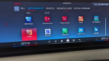
Automobile environments are a special listening challenge with maybe only 15 dB of listening range above the noise while on a busy highway. It is a lousy deal when a listener has to turn the radio volume up and down while hearing radio audio should have come in at a consistent level.
Try it yourself — put an oscilloscope on voice audio in a studio so you to see what you are hearing or observe the waveform in a digital editor. Intentionally record a voice at an audio level that is too high. You will hear the peak clipping distortion, caused by running audio beyond the limits of the equipment, and you will understand that more is not better.
Digital levels
What is standard when recording digitally?
On some devices, the LED VU meter reads –14 dBFS (14 dB below full scale) when audio is normal. On an Axia Radius console, meters change from green to yellow at –20 dBFS and from yellow to red at –10 dBFS. They are peak reading so that helps. Average reading meters will not tell the story. When meters touch the red, there is 10 dB of digital headroom. You might need that or more headroom for an occasional peak.
Remember that 0 dBFS is an absolute limit, and digital clipping is even more destructive than analog. At that point there are no more bits left to represent the signal.
Since noise is no longer an issue, I highly recommend –20 dBFS as a digital reference level for +4 dBm or 0 VU in the analog world, especially when you think that noise might be at –90 dB or more. It is embarrassing and inexcusable to let audio go into audible peak clipping distortion that ruins an otherwise great sound.
I have toured radio studios and watched LED VU meters indicating anything between a consistent –20 and over-the-top red-lined. I’ll bet listeners hear that and tune away. They don’t know why; they just find another station.
Yes, it is true that today’s audio processors do a fairly good job in fixing audio level problems. However, it is up to the production staff and engineers to keep the station plant running so the processing can do its job properly when fed with consistent audio input levels.
Audio pads
The original +8 dBm standard evolved to +4 dBm and now 0 dBm on some studio devices. Many, but not all, analog audio routing switches have audio level controls. If the ones you encounter do not, you should install resistive audio pads to bring higher-level sources down to match the lowest level in the facility.

Fig. 5 shows a simple balanced audio pad. It assumes the audio source has a low drive impedance and all devices being fed by it are bridging (10 Kohm or higher input impedance). The values chosen are standard and are 1/4 watt resistors or larger. Make it variable by substituting a 5000-ohm variable resistor for the 2200-ohm fixed resistor.
Today, many studios have a mix of traditional analog on punchblocks and StudioHub on Cat5. The next step is AoIP, or audio over internet protocol. Audio levels can get out of hand if all sources are not matched.
What about podcasts?
Podcasts typically come to me without any audio processing and often have 10 dB or more disparities between voices during an interview. Some operators deliberately adjust audio level to emphasize a point. This doesn’t go well when listening in a car with high ambient noise. No listener should have to crank the volume up and down to follow the content.
I’ve also noticed a 10 dB or more level difference from one podcast to another, even from one episode to another. Automobile manufacturers should look into simple audio processing for non-processed material like podcasts and CDs. That could enhance the user experience in a noisy road environment.
Consistency is the key to good audio. Take pride in the sound of the facilities you work on. Radio depends on keeping listeners.
Comment on this or any article. Write to [email protected].
Mark Persons, WØMH, CPBE, is a retired broadcast engineering consultant and recipient of the SBE John H. Battison Award for Lifetime Achievement.