Whether you’re aware of it or not, three-terminal voltage regulators automatically adjust power supply voltages in everything from audio consoles to distribution amplifiers to audio processing to STLs to FM exciters to transmitters and to modulation monitors. A circuit designer’s first choice is a single regulator device that can replace a circuit card full of parts that were typical in past designs.
It is true that broadcasting has entered a digital world. Voltage regulators designed into equipment today sometimes use switching technology. They are a bit more complicated in the process of becoming more efficient, but most of the gear in use today employs traditional three-terminal regulators.
What are they?
Three-terminal voltage regulators physically look like a power transistor and act as an automatic variable resistor to bring a supply voltage down to a desired voltage for circuits they power.
Typically, they have 17 transistors in a small package that are a simple answer to get a reliable fixed voltage from power sources that are subject to power bumps, sags and power supply ripple. They might take 24 volts in and regulate it down to 15 volts. That output voltage stays constant with a tight tolerance so the important circuits in electronic devices are not hampered by power fluctuations.
They are analog “series” devices that get warm, as any resistor would, while reducing voltage to a desired value. Ohm’s law: 14 volts in and 5 volts out is a 9 volt drop. If the circuit draws 0.5 amperes, that results in 4.5 watts of heat; hence the regulator needs to be connected to a heat sink.
Fig. 1 shows three regulators, each with three connections, hence the name three-terminal regulators. The ones in larger cases can dissipate more heat. There are other variants, but the one on the left is the most common.
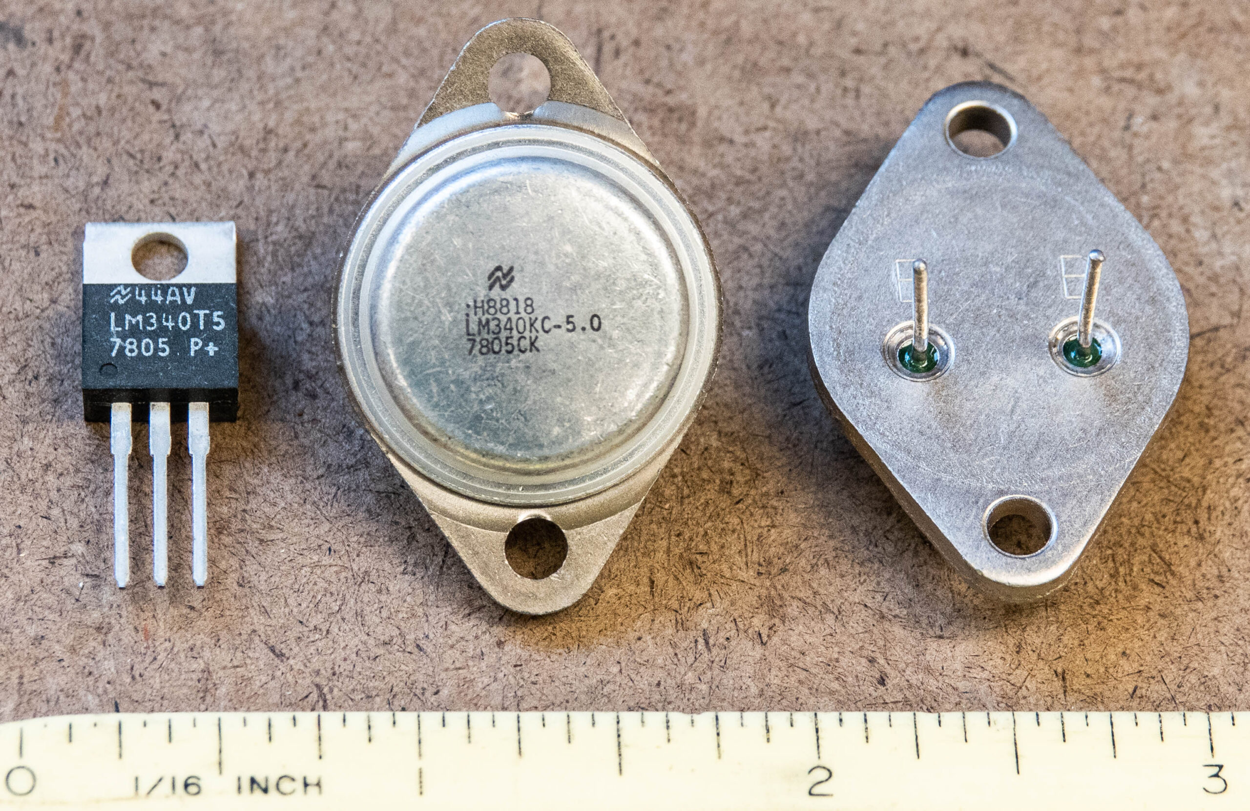
Important information is found in the part numbers. LM340T5 is also known as a 7805, which is a five-volt positive voltage regulator. A 7812 is 12 volts and a 7912 is a 12-volt regulator for negative power supplies. Some are adjustable with a few external components. (Stick with me as there are some important nuggets of information that could make your life easier.)
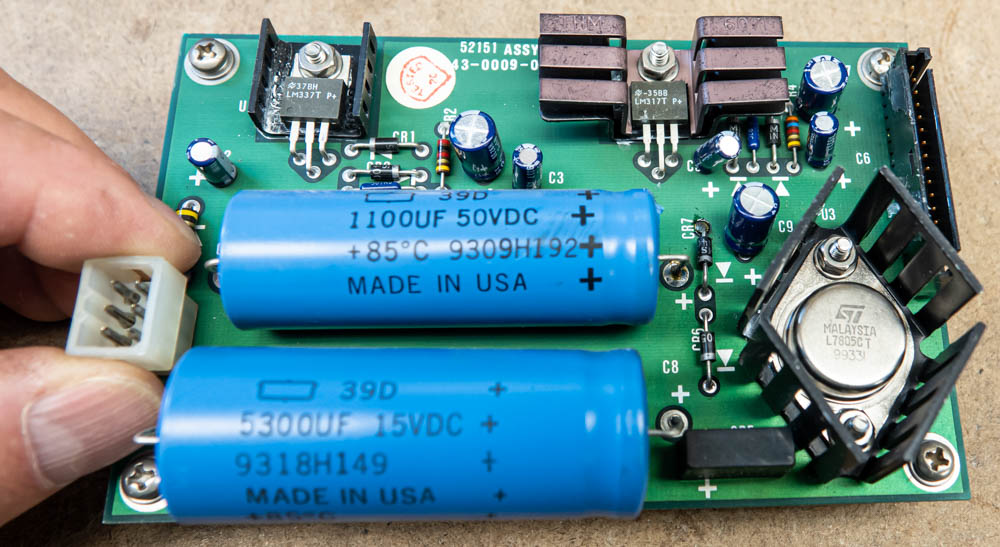
Fig. 2 is a power supply card in a 1990s vintage Continental 802B FM Exciter. As you can see, there are three regulators. One supplies +22 VDC, another –22 VDC and the larger one provides +5 VDC. They are everywhere; this exciter has no fewer than eight of these inexpensive, hard-working circuits.
Things can go wrong
Three-terminal voltage regulators are high-gain devices to keep up with fluctuating input voltages and circuit loads. With high gain comes the possibility of breaking into oscillation and making their own high-frequency alternating current. They will sometimes start oscillating at a couple hundred kilohertz. The regulator will continue to put out its rated voltage, but with an additional 200 kHz or so of unwanted garbage. An oscilloscope will show that. Ouch, the circuits they feed don’t like that. An audio circuit might have a lot of hiss or distortion in it. A green light glowing on the power supply does not indicate all is well. It just shows that voltage is present, regardless of its purity, or lack thereof.
Fig. 3 is a spectrum analyzer view of the RF output of the same Continental exciter, which came out of a Continental 816 FM Transmitter. Yes, it is on the intended 100.7 MHz, but it is also on FM frequencies at about 210 kHz intervals up and down the dial. Now we are taking interference to other stations!
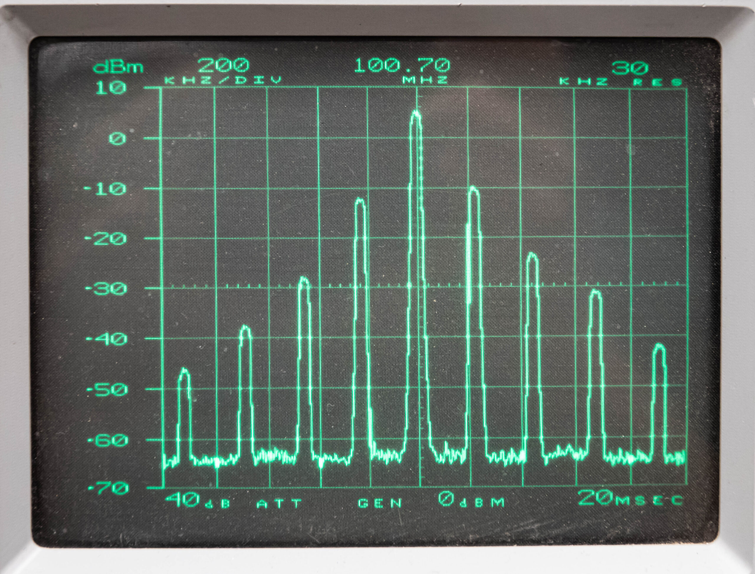
This problem turned out to be a regulator on the exciter’s RF power amplifier board. All was well in the exciter until the RF got to that point. Then the signal was “modulated” by 210 kHz from a regulator gone wild. The culprit turned out to be a 10 mfd electrolytic capacitor that failed by going open. Electrolytic capacitors have a limited lifespan, especially when they are in a hot environment and as years go by.
Fig. 4 shows capacitors associated with two regulators in that module.
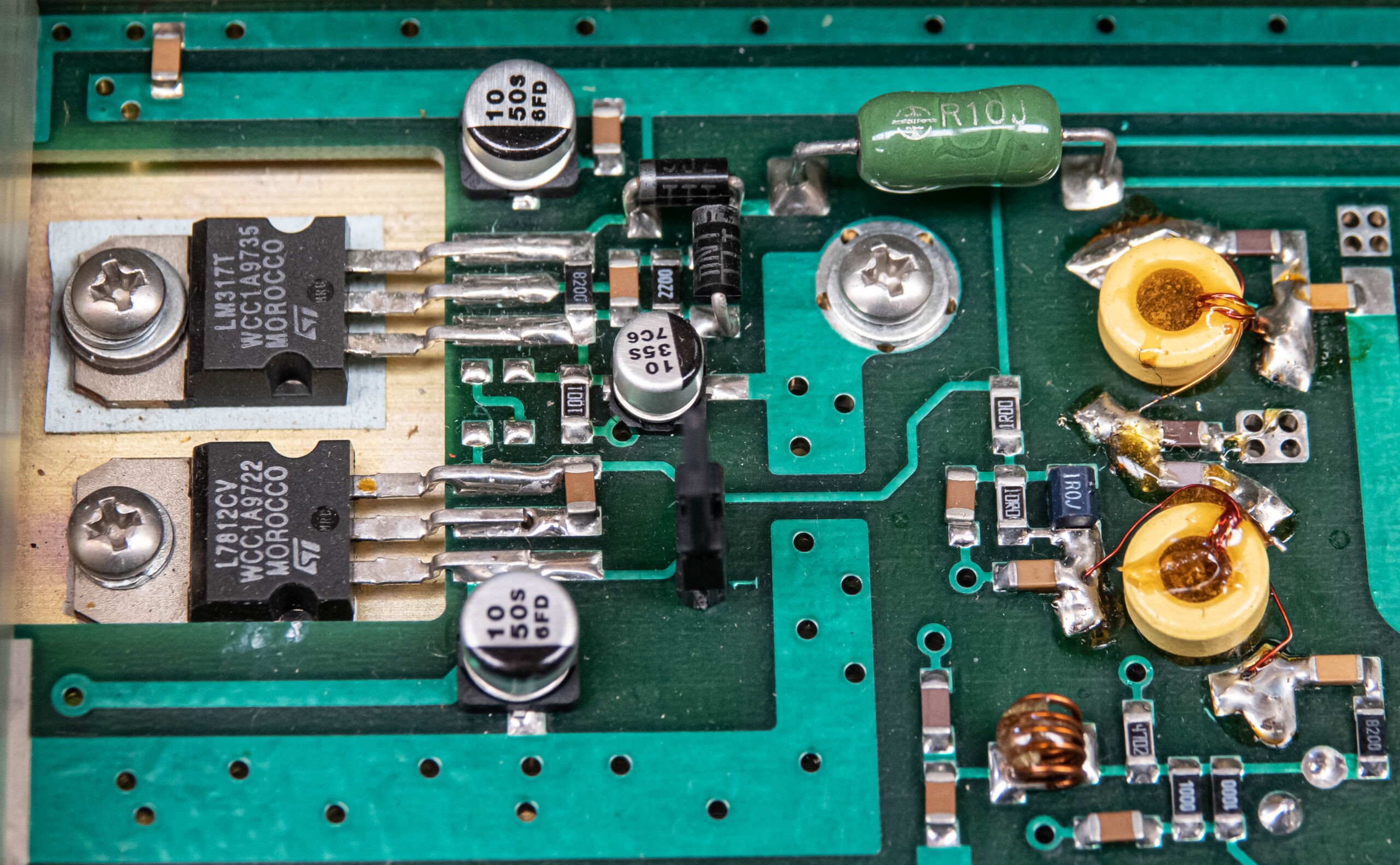
Fig. 5 shows the result when just that one capacitor was replaced. The unwanted signal spurs were gone and just the intended signal on 100.7 MHz came through. In a case like this, I recommend you replace ALL the electrolytic capacitors in that module as others are likely to fail soon.
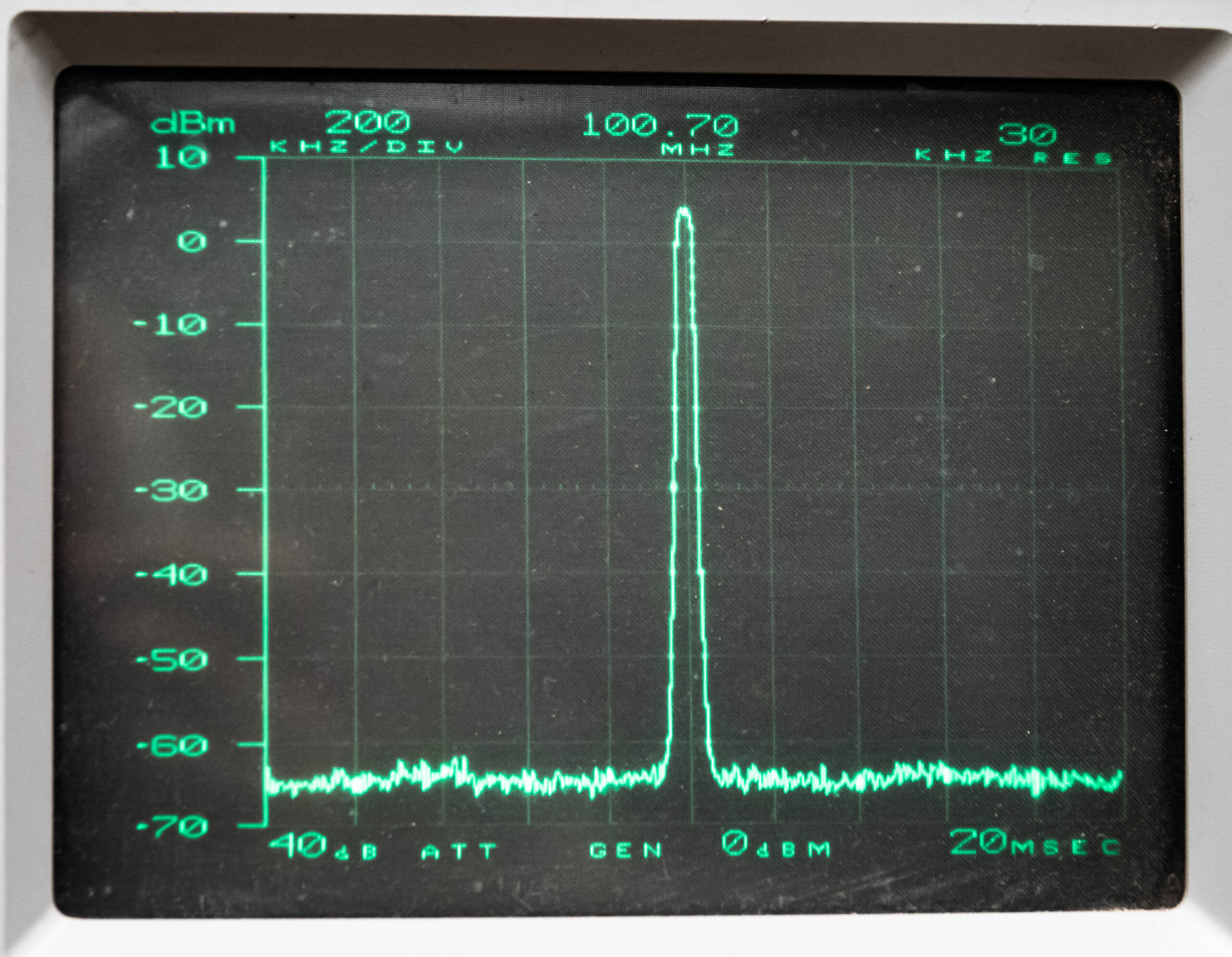
What you are seeing was the exciter running into a dummy load. In a transmitter environment, the troubled exciter was feeding a broadband solid state 400-watt RF amplifier. The signal coming out of the amplifier was likely very similar to what we saw in Fig. 3 because there is no bandwidth limiting. The transmitter’s tube input tuning network, along with tube plate and loading network and then the antenna, likely limited how far up and down the dial the unwanted radiation went. For sure, the station was heard 210 and 420 kHz in both directions from the licensed frequency.
In this instance, the engineer reported the 400-watt RF amplifier metering showed higher than normal reflected power when it was feeding the final tube. He could not tune it out because the tube’s input tuning was mostly allowing the licensed frequency through. Some of the +/- 210 kHz and +/- 420 kHz unwanted spurious signals were reflected back to the amplifier. A spectrum analyzer would have told the story immediately.
But there’s more
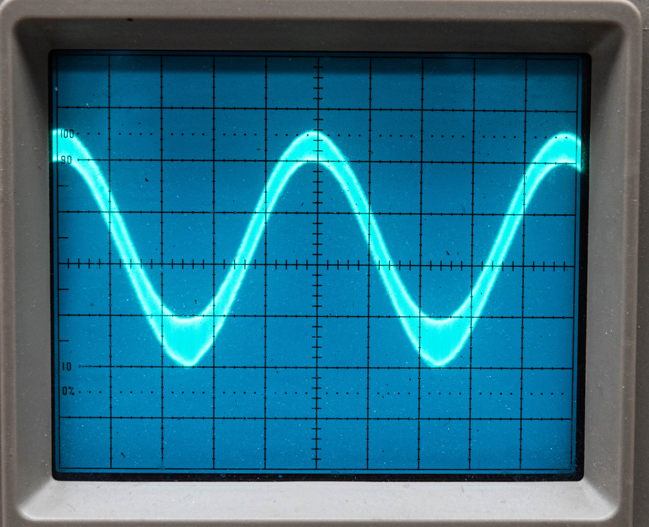
Fig. 6 shows an oscilloscope view of a 1 kHz sine wave tone going through the exciter and being demodulated by a radio. The tone was thick with unwanted 220 kHz riding on it. That’s right, oscillation degrades station audio as well. The waveform became a pure, clean and thin sine wave after the capacitor was replaced.
Capacitors
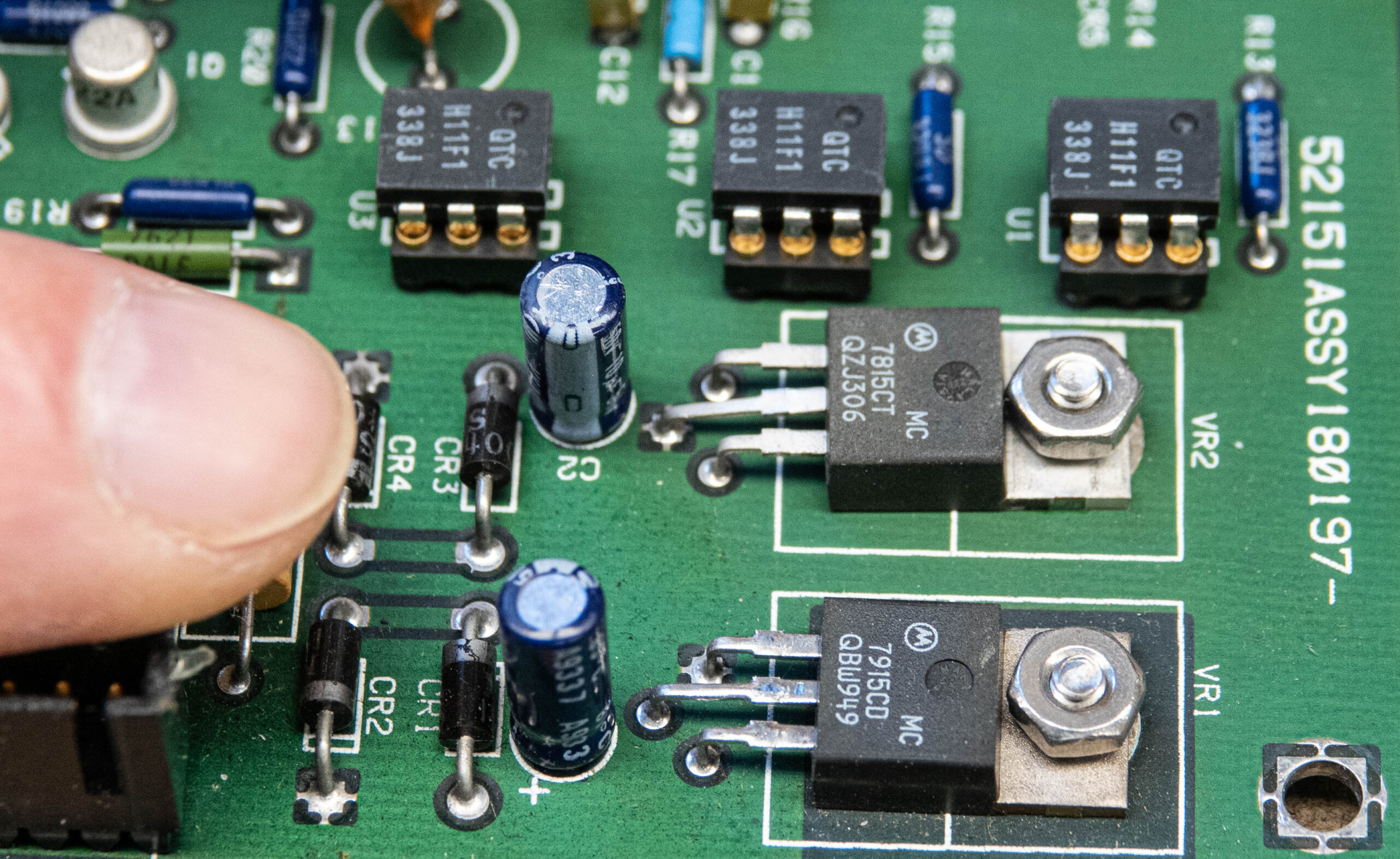
Fig. 7 shows another pair of regulators, with capacitors nearby, on the audio/automatic frequency control assembly of the exciter we are discussing. Circuit designers and manufacturers seem to like inexpensive electrolytic capacitors in regulator applications. They work way past the equipment warranty but fail 10 or so years down the road.
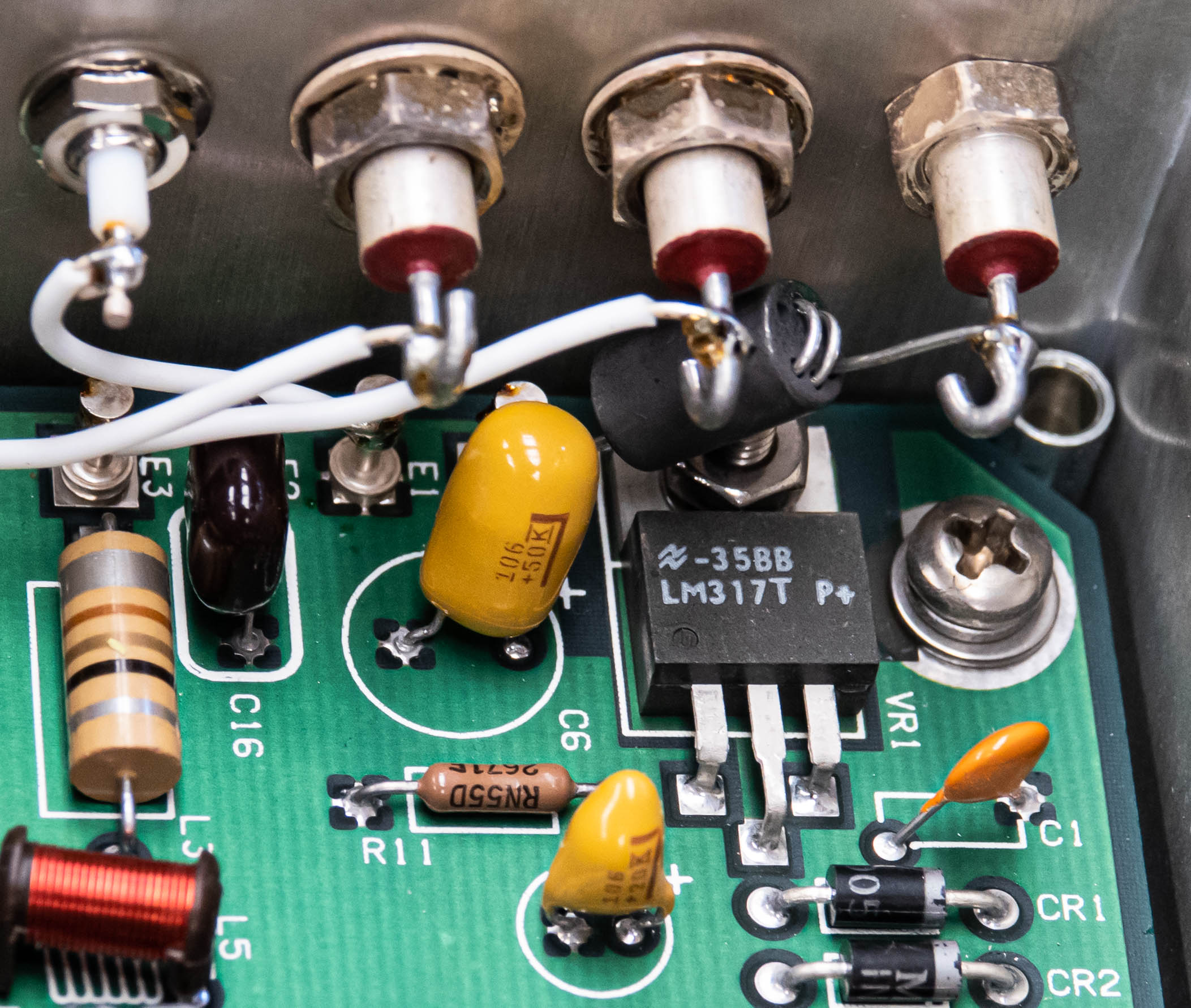
Even the modulated oscillator has one, as seen in Fig. 8. They are everywhere!
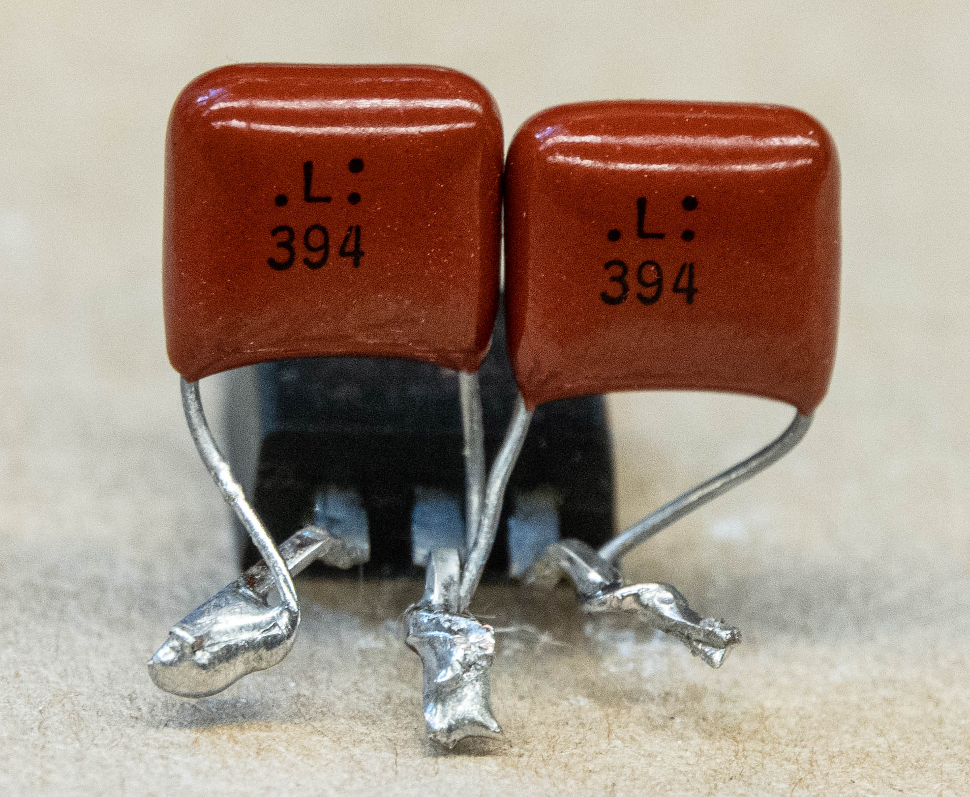
When building something from scratch, I prefer poly foil capacitors which have a much lower ESR (equivalent series resistance), especially at frequencies above 50 kHz. They last forever too. The value I choose for three-terminal regulators is usually 0.39 mfd and I’ve never had a problem. Those capacitors are small enough to mount directly to regulator leads in a point-to-point wiring scheme as shown in Fig. 9.
Learned
The lesson here was replacing one small capacitor saved a $5,000 expense for a new FM exciter, not to mention the hassle of recycling. This exciter will live for years to come.
New regulators
More efficient switching regulators are showing up in recent equipment designs. More power can be handled in the same size component package, but they come with their own drawbacks. Unlike the linear/series regulators that we discussed, these chop up the incoming DC voltage and let the just right voltage out. Capacitors are needed to keep them clean so the outgoing DC power does not have noise riding on it to cause circuit problems.
In summary, be informed about the technology so you can do the best in your broadcast engineering job.