We are fascinated when we see machines work together, seemingly with minds of their own. The TV show “How It’s Made” became popular for simply showing how products are made in an automated factory setting. But behind these machines is a circuit that without it, the whole thing will simply not function. That circuit is called a control system, that magical circuit having the necessary command and control functions that initiate a machine to run and then keep it running properly.

In a broadcast transmitter, the control circuit usually consists of control cards, relays, contactors and a passive or interactive front-panel display system. All of these are connected to enable normal equipment function. Feedback loops in the control circuit prevent abnormal conditions.
It was on my first job as a broadcast technician that I first encountered an elaborate control system used in a piece of transmitter equipment. The circuit was a bewildering array of magnetic relays, wires, nuts and bolts. This was on a transmitter plant with several high-power, short- and medium-wave transmitters.
The plant had a 1980s Continental 100 kW shortwave transmitter (state-of-the-art at the time), and two older transmitters, one of which was a 70 kW shortwave and the other was a 250 kW medium-wave unit.

According to the site manager, the two old units were decommissioned World War II-era CW transmitters from the U.S. Navy. Someone then converted them for radio broadcast.
As you can imagine, I got my hands on both past and present technologies.
The old ones have big and bulky parts. The modulation transformer alone almost reached the ceiling and nearly filled a third of the room. When it was on the air, I could listen to the broadcast audio from the modulation transformer itself!
Amazingly, although the old and the new transmitters were built decades apart, the newer transmitter still used magnetic relays for its control system. The arrangement follows so-called “relay logic,” which was usually presented in a schematic as a ladder diagram. (See Fig. 3.)

In a tube-type transmitter, the control system usually starts with a normally open (NO) and a normally closed (NC) switch to turn on or off a blower relay (Fig. 3). A holding contact from the same relay maintains power to the relay. With the buildup of air pressure in the tube cavity, a pressure switch will turn on the filament transformer and bias supply. After a time-delay run, the system is ready for high-voltage application. Once the high-voltage button is pressed by the operator, the transmitter comes up to full power. If there are any overload conditions, an overload relay will open, cutting off the high-voltage supply to the power tube.
PLC AND MICROCONTROLLER
Using relays alone for the control circuit is fine until a change in the circuit is needed. Rewiring the circuit will incur downtime, which can be costly or impractical. A better system was therefore needed. The introduction of the industrial-grade programmable logic controllers (PLC) made the control circuit less mechanically intensive and became more software-driven (see Fig. 4).

With a PLC in place, a change in the control logic can be done through software with little to no hardware change. The programming of the PLC follows the “ladder diagram” as well, making it easy for technicians and engineers to understand the new system.
For decades, transmitter manufacturers used magnetic relays and relay logic even with the availability of PLC in the early 1970s. The PLC is used widely in industrial systems, but is rarely found in broadcast transmitters. One possible reason is that in a transmitter box, once the control circuit is installed, there would be no more change in the circuit, negating the need for a full-functioning PLC. It was also too complicated to be used for a simple transmitter control system. Last, programming of the PLC needs additional training and resource for the station engineer.
However, there are a few broadcast transmitters that use PLC in their control systems. An example is our 32 kW television transmitter, where three PLCs are used for the control system. The transmitter is a combination of two IOT amplifiers that are both water-cooled with a shared cooling system. Because of the complexity, the designers resorted to PLC to manage all the control functions. The PLCs are very stable, and we never had any problem with them since day one.
Relays and PLCs are meant for big and complicated systems, but for today’s gadgets, the microcontroller is the way to go. It is small, inexpensive and versatile. A microcontroller is a microprocessor with memory, programmable I/Os and other components integrated into one chip (see Fig. 5). The control functions can be programmed into the chip. They are used for specific applications and are in nearly every electronic appliance or piece of equipment that rolls off the assembly line. Microcontrollers were introduced in the 1970s (almost simultaneous with the PLC), and were first used in pocket calculators.

One or more microcontroller can be used in a transmitter. In fact, in our 15 kW solid-state transmitter, 36 ATmega programmable microcontrollers were used. There is one for each of the 24 PA modules, three for the cabinets, one each for the driver stage modules, and one for the switcher.

THE SCADA SYSTEM
SCADA stands for Supervisory Control and Data Acquisition. It is a system not commonly found in the broadcast industry, but which is mostly implemented in large industrial infrastructure like oil refineries, water treatment plants, electrical grids and other industrial systems (see Fig. 7).

There are three core things in SCADA: Supervisory, Control and Data acquisition. In simple terms, Supervisory and Control means monitoring the system continuously, performing a pre-programmed action when needed, and sending alarms as necessary. Data acquisition means saving the data, presenting the current data (on a display system), and it also includes statistical information for data analysis. Their display system has different names such as Graphical User Interface (GUI), User Interface (UI) or Human Machine interface (HMI). GUI is an interactive display and very user-friendly.
The User Interface presents all the important details on the display in the form of mimic diagrams or graphical icons, which is like a block diagram equivalent of the system being monitored. In the example above, the chemical mixing tank is represented by a mimic of the tank with the pressure and temperature gauges.
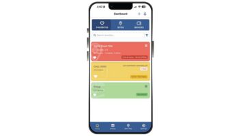
Some remote-control systems (e.g. Burk Technologies) and transmitters also use the GUI for the meter readings, control and status. In one sense, they are similar to a SCADA GUI display.
SCADA in a Broadcast Transmitter
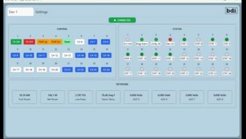
To illustrate how a simplified SCADA display may be implemented for a broadcast transmitter, consider a three-cabinet solid-state transmitter with eight modules per cabinet (see Fig. 8). The driver unit, together with the exciter and low-voltage power supply, is in one rack and the other two racks are for the PA modules.

The display may show an outline of the three cabinets as shown in Fig. 7. Each of the blue vertical rectangles represents an RF power module that contains pallets of amplifiers. When a box is mouse-clicked, the screen will show, at the bottom, all the meter readings of the device or module.
The color also has meaning. In this example, blue means the module is working and red means it is off or defective. The horizontal bar in the middle is for the combiner. The blue color indicates normal and the yellow color indicates lower than normal power output. The box on the left side represents the driver cabinet and shows which driver (and exciter) is in use.
This configuration is like the SCADA display of our four-cabinet solid-state TV transmitter. The transmitter has 24 power modules with a main and standby controller-exciter- driver assembly.
The system monitors several metrics from each of the power module: driver forward power, module forward power, module reflected power, driver drain current, four FET drain currents for each of the four pallets, FET drain DC voltage, VSWR, flange temperature and many others. In all, there are 33 meter readings, 18 status conditions and a calibration command for one module. Thus, for all 24 power modules, there are 792 total meter readings, 432 status conditions plus calibration commands/icons. Additionally, there are also the meter readings, status and commands from the driver cabinet.
With this amount of data to monitor and control, it thus makes sense to use SCADA and serial communication. CAT-5 cables were used for the control signal connections.
The microcontroller in each of the modules is the equivalent of the RTU in an actual SCADA. The stored firmware in the microcontroller is automatically executed on power up and also serves to control its respective module as well as serially communicate with the other units.
Troubleshooting the SCADA
One day, the display was not showing the usual transmitter details except the forward power, reflected power and driver readings. The transmitter was still sending out full RF power, and the video signal was all normal. All the power modules were working as well. We initially thought that there may be a problem on the SCADA computer, or with the signal getting into the computer.
Looking at the other software programs running from the computer, we figured that the problem was not in the computer, but that the signal getting into it was somehow missing or corrupted. I checked all the RJ45 plugs and CAT-5 cables; they were all ok. I was also able to determine that there was serial data signal coming from all the cabinets but it was not getting through to the SCADA computer. The way the switcher, computer and controller were connected was confusing at first, and it was not easy to determine which module was causing the problem.
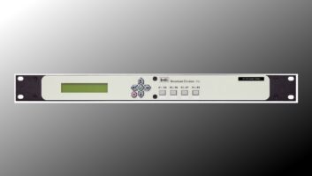
Technical support was difficult at that time because the manufacturer had fallen into hard times. They also did not have the expertise anymore to fix the software system, as this was more the domain of software engineers. However, we managed to have the service manager visit the site, and the first thing he did was to bypass the switcher and connect the serial line from the cabinets to the controller (see Fig. 9). This action somewhat solved the problem because the display came back.

However, because the switcher was bypassed, automatic and remote exciter switchover did not work. At this point, we suspected that the problem was the switcher, and we therefore sent the switcher for repair. They sent a loaner, but when the loaner was plugged in, the display went blank again.
We know that the computer and display were working, so the only thing left was the controller. We then swapped the controller and everything on the display went back to normal. The switcher was working as well. This means that the problem was in the controller itself. Since then, we haven’t had any problem with the control system.
SCADA is a user-friendly means of control and monitoring, especially for complex systems. PLC is ideal for factories, and it is also used within large SCADA systems. But we also saw that the PLC can be used in transmitter equipment.
For smaller systems, one or two microcontrollers can do the job. They are small, rugged and inexpensive. Fixing or replacing a microcontroller can be done, provided that the firmware is also available for download and re-installation.
Finally, despite all the advances in control system technology, good old magnetic relays will not go away soon because they still have plenty of use in control systems, especially in high-power applications. Throughout these developments, the engineer who keeps up with the changes in technology will surely will be up to the task, no matter what control system is in place.
John Marcon, CBRE, CBTE, 8VSB, is chief engineer of Victory Television Network in Little Rock, Ark.
Comment on this or any story. Write to [email protected].