A properly tuned FM transmit antenna is essential for your broadcast system to work properly, yet fewer than 25 percent of engineers tune their FM antennas, based upon my 40 years of observation. Not doing so can increase multipath, reduce coverage, affect loudness and audio quality, increase SCA crosstalk, result in components heating up (which can cause failure of the antenna system) and a whole bunch of other nasties.
Why do engineers not do this? Frequently they don’t realize they have to, or don’t know how to perform the task. Many also believe that because their transmitter’s reflected power is low, things are fine; but this is not necessarily so.
Many, if not most, reflected power meters sample voltage, which means that they are only accurate if their sample is precisely located at a point of voltage maximum (current minimum) in the system; otherwise they will read abnormally low. Another reason the reflected power method is bad is because it only reads the reflected power at the main carrier — and remember FM is not just the main carrier; there are many sidebands, so the antenna measurement should be swept across the entire FM channel.
I once worked for a major-market FM station that ran for over 20 years on a tube transmitter. It showed zero reflected power on its meter. They planned to replace the transmitter with a solid-state unit, which they bought and duly tested under a dummy load. It ran fine for half a day at the required TPO of 8,800 watts. I’d warned the chief engineer that he should get the antenna swept before the installing the transmitter. He did not, and when we put the new transmitter onto the antenna it folded back to 600 watts!
A sweep of the antenna showed why: The antenna was resonant at a frequency 2.2 MHz higher than their frequency, and at their frequency they had a normalized return loss of –15 dB, equating to a VSWR of around 1.43:1. Remember, their old tube transmitter showed zero reflected power the entire time it was in use. After field tuning the antenna (we got the normalized return loss down to –28 dB, which roughly means a VSWR of 1.08:1), the new transmitter came right up at its 8,800 watts full power and only showed 12 watts of reflected.
But the story doesn’t end there. As I listened on the way home that morning, I heard the producer, on the air with the DJ, saying, “Engineering must have done something right — on my drive in, the signal used to ‘break up’ here, here and here, and this morning it remained crystal clear!” This station had been generating multipath for 20 plus years; it was now gone.
In order for an FM antenna to perform at the level for which it is designed, it is necessary to tune it to a normalized return loss of –25 dB or better (equating to a VSWR of about 1.11:1) over the station’s entire 200 kHz channel (if the station is licensed for, say, 100.7 MHz, its channel runs from 100.6 through 100.8 MHz).
There are several ways to do this. The easiest is to use a spectrum analyzer and tracking generator. The generator is set to sweep across the channel, calibrated into an open and short circuit, and connected to the antenna’s transmission line. It will then show the return loss in dB of the antenna.
Return loss is literally the power level (in dB) that is being reflected back down the transmission line from the antenna. If the generator is sending 0 dBm up the line and the analyzer shows a return loss of 25 dB, the power returned to the analyzer is –25 dBm. Realize that because the transmission line has loss also, the round trip loss of the line should be added to the number to determine the true return loss. This is what I mean by normalized return loss.

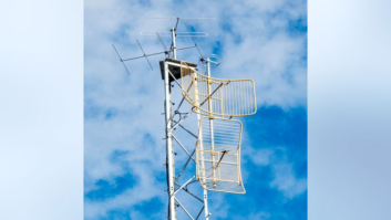
Fig. 1: One bay of a translator antenna as described in the text. You tune it by loosening the nut on the four arms, then sliding a rod in and out at the tip of each bay element.
Courtesy ERI To clarify, let’s assume that the transmission line has exactly 3 dB of loss (50 percent). If the tracking generator is sending out 0 dBm, the power arriving at the antenna is –3 dBm. The antenna then reflects power back down the line, which is again attenuated by 3 dB on its trip back to the ground. This means that a return loss of –25 dB means that the actual return loss of the antenna is –19 dB (–25 plus 6). The line loss is making things look better that they actually are. Return loss can also be used to measure the actual line loss — simply open the line at the antenna, look at the return loss at carrier and divide by two (because of the round trip involved).
I was involved recently in replacing the antenna at an FM translator for a Philadelphia AM station. The FM antenna is mounted atop the AM tower. The directional antenna we installed was made by a major antenna supplier. It is tuned by changing the length of its elements: Loosening a nut and sliding a rod in and out at the tip of each bay element (see Fig. 1).
It was a fairly labor-intensive operation with the two-bay antenna we have (eight total adjustments). Other FM antennas are tuned by moving their bay tuning strap or by adjusting the matching transformer located at the bottom of the antenna.

Fig. 2: Initial analyzer plot of the newly installed, but untuned, antenna.

Fig. 3: The non-normalized plot after field-tuning the antenna.

Fig. 4: The non-normalized return loss reading past the AM isocoupler. We started by first measuring the (round-trip) return loss of the line with the antenna disconnected. Its loss was –3.1 dB. This told us two things: that to normalize our readings we had to add 3.1 dB to the reading that we actually saw, and that the one-way loss of the line was about 1.5 dB. We need this number to set the transmitter power and also to put on the license application.
Once the antenna was installed we did our first (untuned) measurement. The analyzer result is seen in Fig. 2.
The center of the display is the 105.7 MHz carrier frequency. At this frequency the return loss is –13 dB, not very good. Adding the 3.1 dB line loss into this gives us a normalized return loss of roughly –10 dB, corresponding to a VSWR of around 1.8:1. This antenna as supplied will not perform well at all and would probably have 5 to 8 watts of reflected power at the transmitter
The non-normalized plot after field-tuning the antenna is shown in Fig. 3. The lengths of the elements were shortened by one inch. The normalized reading at carrier is –36.9 dB. Also note that the antenna is actually tuned a bit low. The elements could have ideally been reduced by another quarter inch, but it began raining and we wanted to get the crew off the tower. This is still exceptional performance; across the FM channel the normalized return loss is –26.9 or better (around 1.095:1 VSWR)! Also notice the two second-adjacent stations at 105.3 and 106.1 near the tops of the “V”.
Fig. 4 shows the non-normalized return loss reading past the AM isocoupler. The isocoupler is necessary to couple the FM power across the base insulator of this “hot” AM tower. The isocoupler has 0.5 dB loss, so the round trip loss now totals 4 dB. This means that the normalized return loss at carrier is now –31.5 dB. Across the FM channel it is –25 dB worst case (upper end of channel = 105.8 MHz). This is still better then 1.11:1 VSWR). We will likely have the tower crew back to tune the antenna to its optimum in the future.
How do you get your antenna tuned? The best way is to hire a consultant who has the proper equipment and knowledge. Many local consultants can do this. Of course, he must be present while the tower people are there. In our case, we also had to remeasure the base resistance and reactance of the AM support tower and readjust the AM station’s tuning network to match the transmitter (50 ohms). To do both, my consultant cost me a bit under $500 — money well spent, especially when amortized over the length of time the antenna will be in service.
Finally, the transmitter displayed 345 watts forward power and zero watts reflected power. The signal reports are excellent — solid signal with very little multipath all over the city, including downtown Philadelphia, and great-sounding audio (especially the bass — recall that the low frequencies occupy the most bandwidth in FM).
I hope this article has been useful to you. Please, always make sure that you tune your FM antenna.
Dana Puopolo is chief engineer at WGLS(FM), Rowan University in Glassboro, N.J.