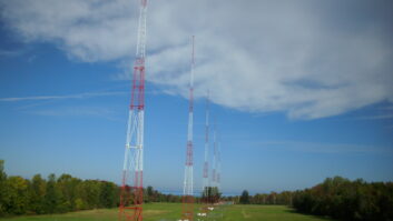
How can you get the most out of your FM antenna system?
Radio World asked three prominent broadcast consulting firms to respond to a number of topics about FM antenna performance. Last issue, we printed their answers to the first two questions. Their replies continue below. More will follow in future issues.
The participants are Ben Dawson of Hatfield & Dawson; Bob Culver of Lohnes & Culver; and Don Markley of D.L. Markley & Associates.
Note that any consultant would need specific site and application information to provide an accurate recommendation for a given situation.
Topic: Impact of antenna sidelobes on multipath performance in the area served by the main lobe of the antenna:
Dawson: Reduction of sidelobes, or even shoulders of the main lobe in the case of antennas with a small number of bays, can substantially reduce foreground reflections, which create multipath, particularly in some environments with high ground reflectivity.
Culver: Multipath reception problems are not caused by the transmitter antenna. They are caused by reflections of the signal anywhere along the propagation path, most likely at intermediate points or closer to the receivers than to the transmission antennas.
But if there are unusual conditions near the transmitter antenna, be aware of them and be prepared to minimize their impact.
For example, if you seek a transmitter site in the mountains and will be below or “in front of” a ridge, you should seek to not send a strong signal into that ridge. If you do, you will build in a permanent and stable signal propagation delay.
It will create some pattern scalloping depending on the strength and phase of the reflected signal. Beside, there will be very poor service beyond the ridge and I hope there is no important population there. If there is, you have the wrong transmitter site.
Similarly, if the transmitter antenna is on a short pole on top of a ridge and a strong side lobe is directed toward the ground nearby and reflected into the service area, the same problem arises. Look for an antenna with reduced side lobes or a taller pole.
In summary, there is very little one can do to correct “multipath” from the transmission end. But you can and should take a careful look at the proposed transmitter site to make sure you are not building a problem into the system.
I have had some anecdotal information that 1/2-wavelength antennas perform quite well. But you must be ready to pay the extra antenna cost, wind load, transmitter power and ERP trade-offs.
Markley: The impact of side lobes on multipath seems to be the fad du jour. We really haven’t seen any proof that this makes a big difference.
Topic: Effects of tower face width, orientation and guys on the pattern performance of a side-mount antenna.
Dawson: Side-mounted antennas should never be used without manufacturer’s measurements of the effects of the specific tower and mounting.
Culver: Everything in or near the antenna aperture will affect the resulting pattern, both the vertical and horizontal plane (horizontal mostly) and both polarizations (vertical mostly).
I did a paper once regarding the “native” patterns or non-directional antennas. That was at the time of the promulgation of the 73.215 contour protection rules.
The element itself has a slight directionality (some, like panels, are highly directional and an omni horizontal pattern is achieved only by the array around the tower axis). Adding the feed line makes it worse. Adding the mounting pole, worse yet. Mounting it on a tower, at what distance and orientation and you get the idea. The resulting pattern can get really bad.
I had dozen or so illustrations of this. The pattern null ranged from about 2 dB to well over 15 dB, the maxima were from a small fraction of 1 dB to over 3 dB.
If you just slap the antenna up, you will not know what you have. You can try to calculate the resulting pattern, but it is tough. You can measure the pattern much more easily, but only in the horizontal plane where a one- or two-bay model is available.
The entire antenna and a longer section of the tower are needed to investigate vertical pattern effects, but they should not be too pronounced because the vertical tower is much larger than the antenna and represents essentially an infinite length reflector in the vertical plane.
Horizontal polarization is affected by the horizontal components of the tower, which can be quite small or can be at a critical dimension and have a serious impact. The vertical structure is always large and affects the vertical polarization in a more uniform way.
Both polarizations are affected by the distance the antenna is mounted from the tower.
Markley: If the most non-directional operation possible is desired, a pole or narrow-face tower is needed, 18 or 24 inches at most.
A tower with a face width of 42 to 48 inches causes terrible pattern distortion. The cross bracing of the tower is approximately 1/2 wavelength long and seem to contribute to significant pattern distortion.
Larger towers, 10 or 12 feet in width, create strange patterns with multiple lobes and nulls that may require some work to make usable.


