SBE certification is the emblem of professionalism in broadcast engineering. To help you get in the certification exam-taking frame of mind, Radio World Engineering Extra poses a typical question in every issue. Although similar in style and content to the exam questions, these are not from past exams nor will they be on future exams in this exact form.
|
We have mentioned in previous Certification Corner columns that many concepts related to even our most advanced technology appeared early on in our tech history. Transmission lines are no different.
Most tech historians think that the path to modern RF transmission lines began around 1666 in Magdeburg, Germany, when Otto von Guericke noted that short threads connected at one end to his primitive electrostatic machine became charged throughout.
This factoid meant nothing to anybody until 1729. Stephen Gray, then 63 and living in a retirement home for men, discovered that small bits of matter could be attracted to the end of a damp string several hundred feet long when the opposite end was touched by a glass tube that had been rubbed by something like mink and taken on an electrostatic charge — a long-distance Thales effect of sorts.
Amazingly, using the physics he divined from these phenomena and experiments, English engineer and mathematician Oliver Heaviside invented coaxial cable. He patented the design in 1880, decades before radio transmissions were understood.
Antennas and Lines
Radio frequency energy is moved through either space or transmission lines. Early work by Marconi and Hertz, among others, recognized that antenna systems could be divided into the antenna itself, which couples electromagnetic waves into space, and the non-resonant transmission line.
The characteristic impedance of a transmission line is the equivalent load presented to the generator by the line. That it is a pure resistance value we ascribe to transmission line as the characteristic impedance, such as 50 or 75 ohms, is a convenient fiction amongst engineers; the reality is a little more complicated. If the generator and load match the characteristic impedance, power is transferred efficiently. However, transmission line has predictable loss, just like a resistor. That loss is related to the metal resistance (usually copper) per length of interest, the capacitive and inductive reactances simplifying out of the calculation.
Nevertheless, when you step back and think about it, where would we be without transmission line? This tool provides us the ability to transit great distances from the generator (the transmitter) to far-flung loads (our antennas) with workable loss and little coloration.
The earliest transmission lines were open-wire. The most basic two-wire (known in ham radio as Zepp wire, see sidebar) is two parallel conductors viewed as balanced whose determinant formula is:
![\[ Z_{O} =276\log\left(\frac{2S}{d}\right)\ \]](https://www.radioworld.com/wp-content/ql-cache/quicklatex.com-d3cb35e383e4a5479d3f14e44956da99_l3.png "Rendered by QuickLaTeX.com")
where:
ZO = characteristic impedance in ohms
S = center to center distance between conductors
d = diameter of the conductors (in the same units as S)
(All logs in formulas are base 10 … we’ll ignore the spacing to other objects such as the ground … some assembly required … not for engineers under 24 … adult supervision required … batteries not included.)
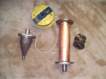
Although the majority of the energy in open-wire line is carried to the antenna or dummy load, open-wire “leaks” some of the signal because there is no shielding continuum to contain all the energy. If there’s sensitive circuitry nearby such as receivers, problems can ensue. To reduce leakage, a set of grounded wires were employed, surrounding the center conductor, and essentially making a two-wire unbalanced system.. As a final step, the outside wires were replaced with copper tubing to provide a complete ground screen around the center conductor.
The center wire or wires inside of this pipe tube soon gave way to an infinite bundle of wires taking the form of a smaller inside pipe with the two pipes coaxially mounted, or coax for short.
The determinant formula for coax is:
![\[ Z_{O} =138\log\left(\frac{b}{a}\right)\ \]](https://www.radioworld.com/wp-content/ql-cache/quicklatex.com-c9f3caf04d1c695337c3e4cfd918b153_l3.png "Rendered by QuickLaTeX.com")
where:
ZO = characteristic impedance in ohms
b = inside diameter of outer conductor
a = outside diameter of inner conductor (in the same units as b), and the insulating dielectric is air
Notice that the multiplier of the coax formula is 138, which is exactly half of the 276 in the open-wire formula. (For extra points, ask yourself, why is this?)
To help you answer that question, ZO can also be determined at high frequencies (say above 1 MHz) from:
![\[ Z_{O} =\sqrt{\frac{L}{C}}\]](https://www.radioworld.com/wp-content/ql-cache/quicklatex.com-8db73b982259e6df3a36bde557be264d_l3.png "Rendered by QuickLaTeX.com")
where:
ZO = characteristic impedance
L = inductance (henrys) per unit length
C = capacitance (farads) per unit length
With this as preamble, let’s get back to our quiz question from last time.
Immediately it appears that answer (A) is correct, as our formula for coax addresses diameters of the inner and outer pipes. Regular readers of this column should be able to spot typical Buc bogus, and (B), (C) and (D) are just that: tech speak gobbledygook. Answer (E) does contain a small issue related to ZO and for that reason is a red herring.
Precision-Built
A stable ZO along the entire length of the line depends on maintaining uniform distance between parallel conductor surfaces. If the insulators are spaced too far apart, the open wires can vary in spacing, and the ZO will change somewhat in that area. Similarly in coax, if the inner coax conductor sags, moving off center, the ZO will also be affected. However diameter values set the ZO; spacer problems can only mildly affect the ZO locally.
Transmission lines are one of the most interesting parts of the science and art of our industry. These have all sorts of qualities worthy of review such as power handling, velocity, mode-ing, attenuation, physical flexibility, etc.
Great sources for elaboration and background include “The ARRL Handbook for Radio Communications,” various manufacturers’ catalogs, Robert Chipman’s “Transmission Lines” in the Schaum’s Outline Series, and, as always, Dr. Frederick Terman’s textbooks.
To recapitulate, the answer is (a), as coaxial cable’s characteristic impedance is determined by the diameters of the inner and outer conductors. The space encapsulated by these two surfaces is the most active part of the coax and where the majority of signal is propagated.
A principle reason these specific inner and outer surfaces are exactly delineated in the coax formula is skin effect, about which you can read more in one of our previous columns, which you can find at “At RF It’s Only Skin Deep.” Again, you’ll notice the involvement of the distinguished Mr. Heaviside. And if you would like to work further with the interaction of these surfaces, a nifty coax line calculator also is posted at Coaxial Cable Impedance Calculator.
Zepp Me Up, Dear
The most basic two-wire is known in the vernacular of ham radio as Zepp wire because it is so often used with Zeppelin-type antennas.
In flight, German Zeppelins like the Hindenburg would unroll a trailing antenna of two parallel wires behind the craft. One wire of the pair was truncated exactly one-quarter wavelength of the frequency in use, with the second conductor continuing on another half-wavelength, creating a simple and efficient quarter-wave matching system. Evidently, this arrangement minimized arcing, which was anathema to a hydrogen-filled airship. These craft also made extensive use of mercury encapsulated switches to contain the contact arc, including the Morse key.
|
Charles “Buc” Fitch, P.E., CPBE, AMD, is a frequent contributor to Radio World. Missed some Certification Corners or want to review them for your next exam? See the “Certification” tab under Columns at radioworld.com.