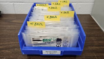
(click thumbnail)Figure 1 : A coupling network consisting of coils and capacitors.We wrap up our transmitter site inspection with some tips for engineers who manage AM arrays.
At the base of each tower sits a “doghouse” – sometimes a building, sometimes just an aluminum box. The components housed within match the tower impedance to the 50-ohm impedance of the transmission line. In directional arrays, you may find more components or networks used for Day, Night , or Non-Directional modes.
With another person on site with you, inspect the interior of these networks. Before you begin to inspect, make sure that the power for the station is off, the transmitter door is open – to keep the interlock open so the transmitter is not accidentally turned on – and the remote control is in Local.
Take with you a can of bee spray, foaming sealant, 3-in-1 oil, a strong flashlight or trouble lamp, some damp rags and a vacuum.
The locks on coupling networks may be either a padlocks or internal locks. In either case, lubricate the lock mechanism thoroughly with the oil. Pay attention to tThe locks should be paid attention to before it the weather turns is cold and snowy.
Once inside, it is time to clean and inspect. Many coupling networks have an AC plug, so use it for your vacuum and trouble lamp.
No AC? Use the flashlight and damp rags. Before you begin the inspection, a few precautions.
First, open the J-plug on the tower side of the network. T – that will prevent any re-radiated energy from coupling into the tower and into the network while you work.
Open the incoming J-plug, just to be safe. As you remove these plugs, did they just slip out or did you have to work at it?
You want a tight connection here, so if the plug slipped out, tighten the spring blades by squeezing them together with a large set of pliers. Don’t twist or rotate the blades because some J-plug jacks are soldered and the prongs of the jack will break off.
Inside the coupling network, you may have a light socket. If there is no switch, unscrew the bulb slightly when you are done. This will save on the bulb life. It’s also a good idea to Also, keep a spare bulb on the floor of the ATU in its cardboard case.
With your vacuum or rag, dust the components, remove all cobwebs, rodent and bee nests.
As you work, you will encounter a number of different components that you’ll need to both clean and inspect. Coils are first.
As you clean and dust each coil, be careful not to jiggle or move any of the copper straps that tap the coils. You might grab each tap to einsure they are tight, but do not change their location.
If you have a permanent marker, place a mark on either side of the coil clip, so you’ll know where it belongs should it fall off. If rotary coils are used, inspect the wheel that rotates around the coil ribbon or tube.
Age and arcing can damage or destroy the ribbon or tube. Failure can be disastrous, so look for pitting or burn marks.
All connections into and out of the coil should be snug, but do not over- tighten. If the hardware used for the connections has discolored – usually showing a green tinge – replace it.
Corrosion on connections can cause intermittent problems. Your time is better spent replacing the corroded hardware than searching for intermittent faults.
The issue of hardware is an important one, – be it AM or FM.
Steel hardware is affected by the RF frequency. The steel will heat up as it absorbs the RF. Ferrous hardware will drive you crazy trying as you try to track down what’s wrong. Use only brass or nickel-plated brass hardware – that includes washers, as well as bolts and nuts.
This hardware is made up of non-ferrous metals. Don’t just grab a bolt or screw off the workbench for tightening or securing things in the RF chain – the results can be disastrous!

. . .
Maintenance of capacitors is the next issue.
The ceramic body should not be cracked. Vacuum capacitors should be clear, – not cloudy. The interior metal plates should be shiny as you view them through the glass.
As with coils, check all hardware should be checked for tightness. Loose hardware makes for a poor electrical connection. Heat will build up at the loose connection and eventually will eventually cause failure or component damage.
Don’t over-tighten the hardware but make sure it is snug. Over-tightening vacuum capacitor brackets can cost a fortune. Handle these components carefully. For best results, use the factory-supplied mounting brackets or clips.
Some capacitors and most coils are mounted on standoff porcelain insulators. These insulators can crack or break. Moisture and dirt accumulate in the cracks and can lead to unstable performance, arcing and failure.
When tightening hardware mounted in porcelain insulators, always use a fiber washer on each end of the insulator. And remember, this is ceramic. It will break under stress. Don’t over-tighten.
Do not move any of the copper pipe or strap connecting the various components. Clean them off with the damp rag or vacuum but do not change the physical location.
. . .
(click thumbnail)Figure 2 : A static drain choke should show no signs of burns or arcing.
RF contactors switch components into or out of the circuit. Inspect the contacts for signs of “hot switching.” When a contactor is switched while transmitter power is applied, contacts will burn. Eventually, they will fail.
Inspect the linkage of the contactor as well. In order to get the contactor to switch, have your assistant switch the mode switch at the transmitter building.
Movement should be swift, not sluggish. Sluggish movement may point to worn or binding linkage assemblies.
If you have a directional station that uses contactors, have at least one replacement contactor on the shelf. Contactors play an integral part in the AM array and losing one can keep you off the air for an extended period of time.
Finally, inspect the static drain choke or tower lighting choke for burns as shown in Figure 2. Any sign of discoloring should be investigated.
As you button up the box, a few final thoughts.
(click thumbnail)Figure 3 : All components are labeled in this coupling network.
First, make sure all components are identified. The manufacturer labeled each part in Figure 3, so they are easy to locate on the schematic.
What happens if you don’t have a schematic and the parts are not labeled?
Draw out the circuit and identify the parts yourself. You may need to redo the drawing several times. Once you’ve got the schematic drawn, you’ll need to identify the components.
Newer coils usually have a label or plate on one of the triangular supporting struts. Capacitors are usually are labeled on an end plate.
Remember to write down the capacitor values. The label identifying the capacity of the capacitor often is often damaged when these components explode. Having this information beforeahead of any disaster strikes will help get you back on the air quicker.
Once the components are identified on the schematic, put a copy in a plastic page protector and tape it to the wall. Keep another copy up at the transmitter building, as well.
If you’ve done this work at night, before closing the cabinet, get your assistant to stand outside of the enclosure. Sweep your flashlight or trouble lamp around inside the box and ask your assistant to watch for any light leaks. Seal any holes with the foam sealant you brought along. Cable entry holes should also be sealed.
Coupling network maintenance is time- consuming but, when thoroughly performed, it can be doneyou can do it just once a year. Keeping the box clean and weather tight is half the battle.
Submissions for this column are encouraged and qualify for SBE recertification credit. Fax your submission to (703) 323-8044, or send e-mail to [email protected]