Harry Bingaman is former director of engineering for Sudbury Broadcasting in Pennsylvania. Harry retired last fall from the group but stays active doing contract jobs, working the ham bands and enjoying his grandchildren.
When Harry had an issue with an MCI-6100 Series Coaxial Transfer Switch, he came up with a diagnostic aid to share with Workbench readers.
His problem was that the MCI coaxial transfer switch would not do a switch from position A to position B. Harry removed the cover from the switch and located the latching relay that controls the changeover. The latching relay voltage on this unit was 12 VDC and only requires a momentary pulse to latch the relay one way or the other.
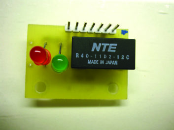
The latching relay is mounted on a small circuit board with a Molex-brand connector with several wires that provide switching voltage to the position motor and 12 VDC control pulses from the remote control. The board and relay are rather small, and it’s tough to connect a voltmeter to ensure you have a voltage pulse to the latching relay.
To further complicate troubleshooting, most coax switches are located in a place that requires a ladder, a third arm and a distant reach from the remote control. If you look carefully at this board, the relay is a solder-in type, and the circuit board has six unused holes to its side.
[Making Sense of Component Level Troubleshooting]
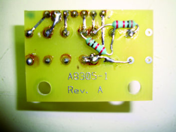
This gave Harry the idea of mounting two LEDs in those spare holes (Red=A; Green=B) with the appropriate dropping resistors to give him a visual indication that he is getting voltage to the relay latching coils at least. There is plenty of room inside the switch housing to accomplish this task.
Harry used super-bright LEDs so he can see them from the other end of the transmitter room, where the remote control is located. This makes observing the position easier when toggling the remote control from position A to position B.
If you need to replace the latching relay, Harry suggests including an IC socket rather than the standard solder-to-the-circuit-board arrangement. This would make relay replacement a little quicker if ever needed. This latching relay is rated at 2 Amps, and normally hangs in there for a long time.
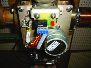
As Harry diagnosed his problem, he found the latching relay had a coil “A” open.
Harry offers one word of warning — when working on this latching relay control board, make sure you disable the 110-volt control to the position motor. You don’t want the motor changing the RF path by accident. You’ll also want to make sure the control relay is latched to the same position as the Position motor on the coax switch before reassembly and power-up.
Harry offers this warning if you did not connect all of the appropriate transmitter interlock connections to the coaxial transfer switch. Remember, no hot switching is allowed!
[Shine a Bright Light on the New Year]
If you haven’t connected the interlocks for both the main and auxiliary transmitters, please take the time to do this. Over the years, Harry has seen the result of hot switching at more than a few stations, where all that was connected was the connection for a switch from main to aux.
The thinking was that whoever would make the switch would be intelligent enough to power down all systems first. This is a bad assumption and also an expensive one!
Take the time to make the interlock connections. The extra time will save you a lot of headaches down the road.
Workbench thrives on your tips and other great ideas. Help fellow engineers and qualify for SBE recertification credit. Send tips and high-resolution photos to [email protected].
Author John Bisset has spent 49 years in broadcast and is still learning. He handles western U.S. radio sales for the Telos Alliance. He is a past recipient of the SBE’s Educator of the Year Award.
