Situation: You’re an IT person new to radio broadcast engineering and are given the keys to an AM transmitter site. The manager says to go out and get familiar with the equipment.
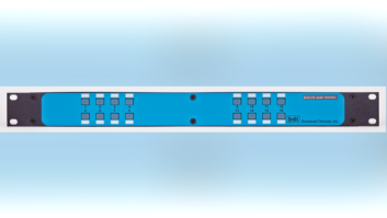
The site reminds you of a Frankenstein movie, especially when looking into a phasor cabinet or an antenna coupling network at the base of a tower. There are huge metal coils and fist-size blocks of black or white mystery parts that have no relation to the IT profession you were trained for, as in Fig. 1.
What does this all mean?
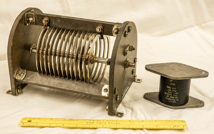
Large RF capacitors are used in AM antenna phasors, antenna coupling units, filters and in transmitters. Troubleshooting can be easy half of the time (Fig. 2). That is when it is obvious that a capacitor has overheated, maybe even caught fire and smoke leaked out, as we say. This G2 series capacitor is an older version of the 292 black capacitor shown in Fig. 1.
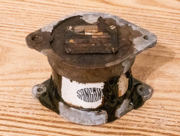
A failed .001 mfd capacitor (Fig. 3) can be replaced by two .002 mfd capacitors connected in series. If the .001 was rated at 10 amperes of RF current, the .002 capacitors must be able to handle 10 amperes each. If the .001 capacitor was rated at 10 KV, the .002 capacitors only need to be able to handle 5 KV because each is seeing half of the circuit voltage.

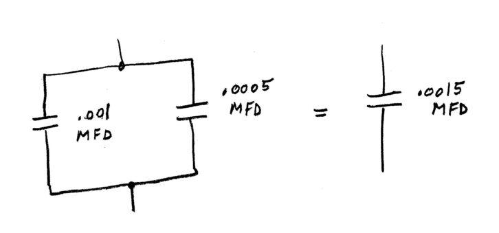
You can also replace one capacitor by putting two capacitors in parallel as shown in Fig. 4. In this case, a .0015 mfd capacitor can be replaced by a .001 mfd and a .0005 mfd in parallel. Each must withstand the circuit voltage that the original .0015 did, but the RF current is divided between the two. The .001 mfd will handle two-thirds of the RF current in amperes. The .0005 capacitor will be required to handle one-third. That is because .001 has electrically half of the RF reactance that the .0005 has.
On the practical side, no two capacitors are identical. You might find a small tuning difference, even when replacing a single capacitor with a factory new one.
Troubleshooting capacitors
Let’s look at the reason a capacitor in the AM example might have failed. Maybe it was lightning damage. If so, were the arc gaps set properly? I discussed these in a 2017 Radio World article.
Assuming the arc gaps are doing their job, you should investigate the circuit design. It might take a consultant to figure it out. For sure you will want a consultant if the same capacitor fails twice.
RF resistance in capacitors is termed as capacitive reactance and it changes with frequency. The reactance of a capacitor will be less at higher frequencies. For example, a .001 mfd (1000 picofarad) capacitor is 159 ohms at 1000 kHz, the middle of the AM broadcast band. It is 106 ohms at 1500 kHz and 294 ohms at 540 kHz. You can measure the microfarad value with some multimeters, but not the reactance.
Similarly, a 10 uhy (microhenry) coil AKA inductor will have 63 ohms of inductive reactance at 1000 kHz. At 540 kHz it is 34 ohms, then at 1500 kHz it is 94 ohms. As you can see, the inductive reactance increases with frequency, just the opposite of capacitive reactance.
Connecting two coils/inductors in series gives you a larger inductor, just add the two inductance values together. There is no practical use for paralleling inductors that I can think of.
These similarities and differences make it possible to design broadband RF networks and very narrow circuits for filters.
In the past I calculated ohms of capacitive or inductive reactance on paper. Now a Google search will bring me to a calculator to find the value either going from capacitance or inductance to reactance or in reverse. Easy enough.
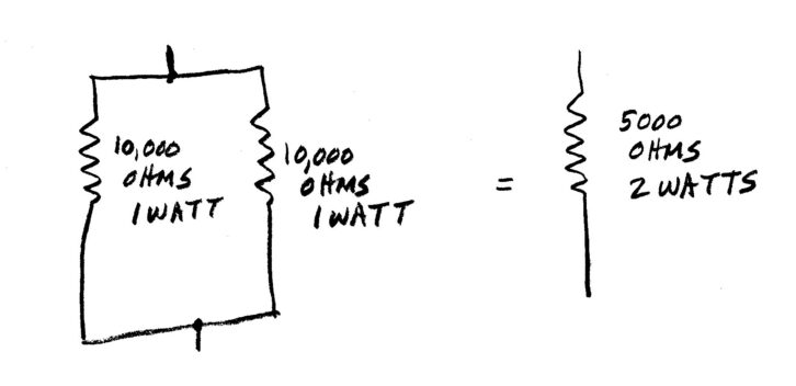
Let’s look at resistance in a resistor. For all practical purposes it doesn’t change with frequency. (Fig. 5.) Say you need a 5000 ohm/2-watt resistor to replace a failed one and you need it now! Well, a pair of 10,000 ohm/1-watt resistors in parallel will be an exact electrical equivalent, even if they look a little different.
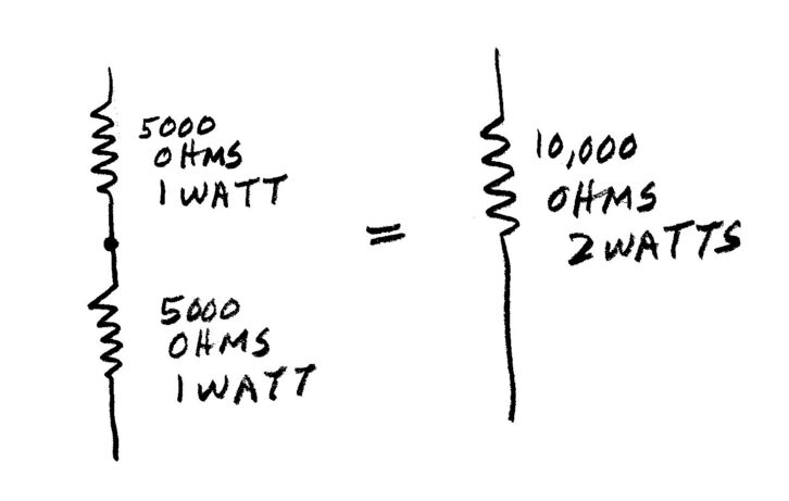
The same applies to resistors in series (Fig. 6).Two 5000-ohm resistors, wired in series, become a 10,000-ohm resistor. If each of the 5000-ohm resistors is rated at 1 watt, the total is 2 watts over the 10,000 ohms.
Prove it for yourself using a multimeter on spare resistors to get a feel for how this works before you must put it into practice. I carry an assortment of resistors in my tool kit to take care of situations like this without resorting to ordering a replacement component that could take days to get. Remember, Radio Shack is no longer just down the street! It might be a temporary cure until an exact replacement arrives. Then, do the right thing. Take the time to make it look like factory original.
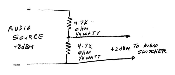
Back at the studio, let’s say you want to create an audio attenuator to bring down an audio level that is too high for the equipment it is feeding. Possibly it is an old analog news or production studio console that might feed into an audio switcher.
If the console has a +8 dBm output, its peak audio level is +28 dBm at clipping and likely 10 dB or more above clipping on the audio switcher. Audio peak distortion happens. Ouch!
I described this in a 2023 Radio World article, “Let’s Talk About Some Basics of Audio for Radio.”
As mentioned then, a 600-ohm terminating resistor will likely be required if the console has an audio output transformer. That will keep the frequency response in factory specification. Then an audio attenuator or two can be used to reduce the level to something acceptable for some equipment. A simple series resistor circuit should suffice. Fig. 7 is a classic voltage divider. The output voltage will be at half of the input voltage, which is 6 dB lower than the input.
In summary, resistors, capacitors and inductors are easy once you understand the basics. Now you can go out into the radio broadcast world with more confidence to diagnose and solve engineering problems.
Comment on this or any article. Write to [email protected].