Like it or not, at some point in your career you’ll probably need to keep an aging transmitter running.
Among the complaints about older AM rigs is their inability to modulate. The problem usually is traced to weak or “soft” modulator tubes.
Lyle Henry, an SCA consultant in Los Angeles and an international contract engineer, offers an interesting test to verify the modulating capacity of older transmitters.
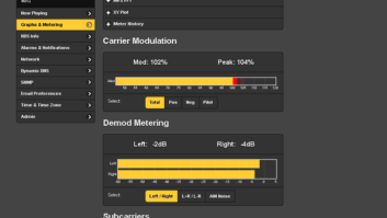
Bypassing the processor and feeding the transmitter input with an audio oscillator, measure the voltage (VU) required to modulate the rig at 25, 50 and 100 percent. As you measure, remember that 50-percent modulation should be twice the voltage (+6 dB) from 25 percent, and 100 percent should be twice the voltage (+6 dB) from the level at 50-percent modulation.
Lyle reminds you to use a VOM to measure the voltage going into the transmitter from the audio oscillator, and not depend on the metering of the audio oscillator. Some of these built-in meters aren’t reading the true output; other oscillators lack a metering function altogether.
This audio test will tell you if the transmitter has a gain compression problem. With a scope, you can trace the signal through the transmitter stages. When you feed tones into the transmitter using this method, check the modulation over a frequency range of 100 Hz to 8 kHz. Even an old decrepit transmitter should be reasonably flat over that range.
Stan Carter, chief at WJNT(AM) in Jackson, Miss., digs a little deeper. By checking the values of the modulation transformer, the modulation reactor, and the high-voltage capacitors, you’ll know that the guts of the modulation circuitry is working properly.
Another point to consider is the feedback resistor “ladders.” If these resistors open up, the transmitter’s ability to modulate fully will be affected.
. . .
(click thumbnail)Fig. 1 The generator is on the roof, protected by an ice shield.
(click thumbnail)Fig. 2 Also shielded from ice is the cabling conduit (arrow). Dual air conditioners are visible on the wall.
Jeff Caudell, market engineer for the Harrisonburg, Va., Clear Channel Group, just completed a new transmitter site using GFRC Shelters from Louisiana (www.gfrc.com).
GFRC stands for “glass fiber reinforced concrete.” This company joins the popular VFP (www.vfpinc.com) in providing hardened buildings for communication applications such as transmitter sites.
In addition to the aggregate finish, the concrete construction and a steel frame permit using the roof for a generator, as seen in Fig. 1.
This is a leased site with a heavily loaded tower, so Jeff and regional engineer Ben Brinitzer specified an ice shield to protect the generator from falling ice. Even cabling conduit from the generator is protected with its own ice shield, as seen in Fig. 2. Dual redundant air conditioners, also seen, keep the inside clean and cool.


. . .
Tower light monitoring is like taxes. No one wants to dwell on the subject, but we all have to comply with the rules, or else.
Unfortunately, tower light telemetry always seems to end up at the bottom of the list. Tower light monitoring can be ugly.
Ray Fantini does contract work for a number of stations on Maryland’s Eastern Shore. He has come up with a three-step process in cleaning such messes and shares them with Workbench readers.
Almost every incandescent system uses current-sensing transformers placed in line with the feed to the tower. The transformer senses the current pulse when the beacon flashes. The transformer will get a small voltage induced in its secondary every time the beacons flash, as well as a small voltage from the continuously burning obstruction lights.
Perhaps the simplest, though not necessarily the most accurate, method of monitoring is to rectify the voltage from this sampling transformer and send the signal to a metering channel on the remote control. In the days of hard-wired remote control systems, the meter would pulse as the beacon flashed. Another method was to tie the output through a diode to the remote-control status channel, causing the status light to flash.
Nowadays, Burk/Gentner and Sine dialup remote control systems are the norm, and the challenge is to use the sample transformer output to drive a status channel.
Ray’s first step is dealing with the sample transformer. To drive a status channel, you need a fairly good output from the transformer, on the order of 3 to 4 volts. Sample transformers are available in several ranges; the lower the current, the higher the output. It’s important, therefore, to figure your load into the calculations.
A couple of 600-watt beacon lamps and two 100-watt obstruction lights will only pull about 12 or 13 amps total; therefore, a 50-ampere sample transformer won’t give you enough voltage. Ray tried a 30-ampere transformer instead.
Keep in mind that some of these sample transformers have a soldered tap that sets their range. Too low an output? Try looping the wire that passes through the toroid a second time. This doubles the primary sample.
The second step is dealing with the status channel. It wants a DC input, so rectify the transformer sample with a diode (ECG-125).
Next is the need to provide a constant high-level input to the channel. We want the signal to be high the whole time the light is working, but go low when the light has been off for more than 20 or 30 seconds.
Place a good-sized capacitor (470 uF to start) on the status input. Every time the light flashes, the pulse from the transformer via the diode will charge the capacitor and hold the status line high. When the light stops flashing, the pulse will no longer charge the capacitor and it will discharge, dragging the input low.
Ray found that by putting a 50-kohm variable resistor across the charging capacitor, the discharge rate can be controlled. This permits you to adjust the rate so that after the loss of a couple of pulses, the status line is dragged low.
If you’re monitoring lights at an AM site, Ray cautions to add a decoupling capacitor across the input of the diode and status channel. The AM carrier will keep the input high all the time.
The third step is to program the remote control software. The channel needs to be set to mute as a time of day function. Mute the status channel during the day, and set it to generate an alarm when the status line goes low.
Ray was able to reduce all this to a little breadboard. Reach him via e-mail to [email protected].
Submissions for this column are encouraged, and qualify for SBE recertification credit. Fax your submission to (703) 323-8044, or send e-mail to [email protected]