The author is technical director for Radio Wrocław.

WROCŁAW, Poland — Regional public broadcaster Radio Wrocław together with Wrocław University of Science and Technology and Poland’s National Institute of Telecommunications are running a single frequency DAB+ network for small and local broadcasters in the city of Wrocław and the surrounding vicinity. The tests began in 2015 and will continue until the end of 2019 with a possibility of continuation.
THE SETUP
For our purpose, the project team created an economical-yet-complete solution, consisting of a small-scale DAB+ headend to facilitate access to this digital radio platform for local and small broadcasters.
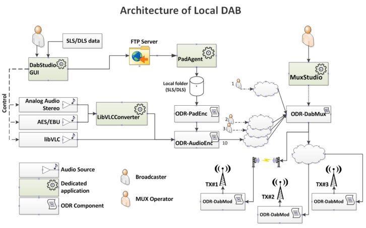
The solution is based on open-source software, which is a modified version of Opendigitalradio resources. It comprises audio encoders, PAD encoders, multiplexer and modulators working with USRP cards at three transmitting sites. Currently, 10 services are broadcast over the network along with additional data in the shape of DLS (text) and SLS (graphics).
We expected that, once we switched on all three transmitters of the SNF network in Wrocław, we would have great coverage in the city center. Unfortunately, we were in for a surprise. While the quality was good in the northern part of the city, we had some issues with coverage in the southern part: Dropouts, signal loss and interruptions occurred, even near the transmitters.
At first, we thought the problem was due to signal distribution because the network uses a regular internet connection as the main link between all 10 radio stations and the local DAB multiplexer located at the university, as well as between the multiplexer and two of the three transmitters. A microwave link in the 5 GHz band feeds the third transmitter.
We chose to implement a regular internet connection to provide a realistic scenario for smaller radio stations, in which owners usually can’t afford to pay hefty sums for advanced links with high QoS. But at the same time, these stations need a solid solution to get their broadcasts out.
CHALLENGES
Initially, many problems arose. The optimization of internet-related issues was a huge challenge. Fortunately, we were eventually able to make some headway, although the breaks and gaps proved to be frustrating for the project team: It was difficult to figure out why, in the overlapping coverage area of two transmitters (where according to coverage analysis and expected SFN gain we should have had perfect reception), we had very bad or no reception.
“Children in the fog” is a good description of the project team members as they scrambled to find the cause of such a disastrous situation. Of course, we suspected transmitter synchronization problems, but there was no way to prove it.
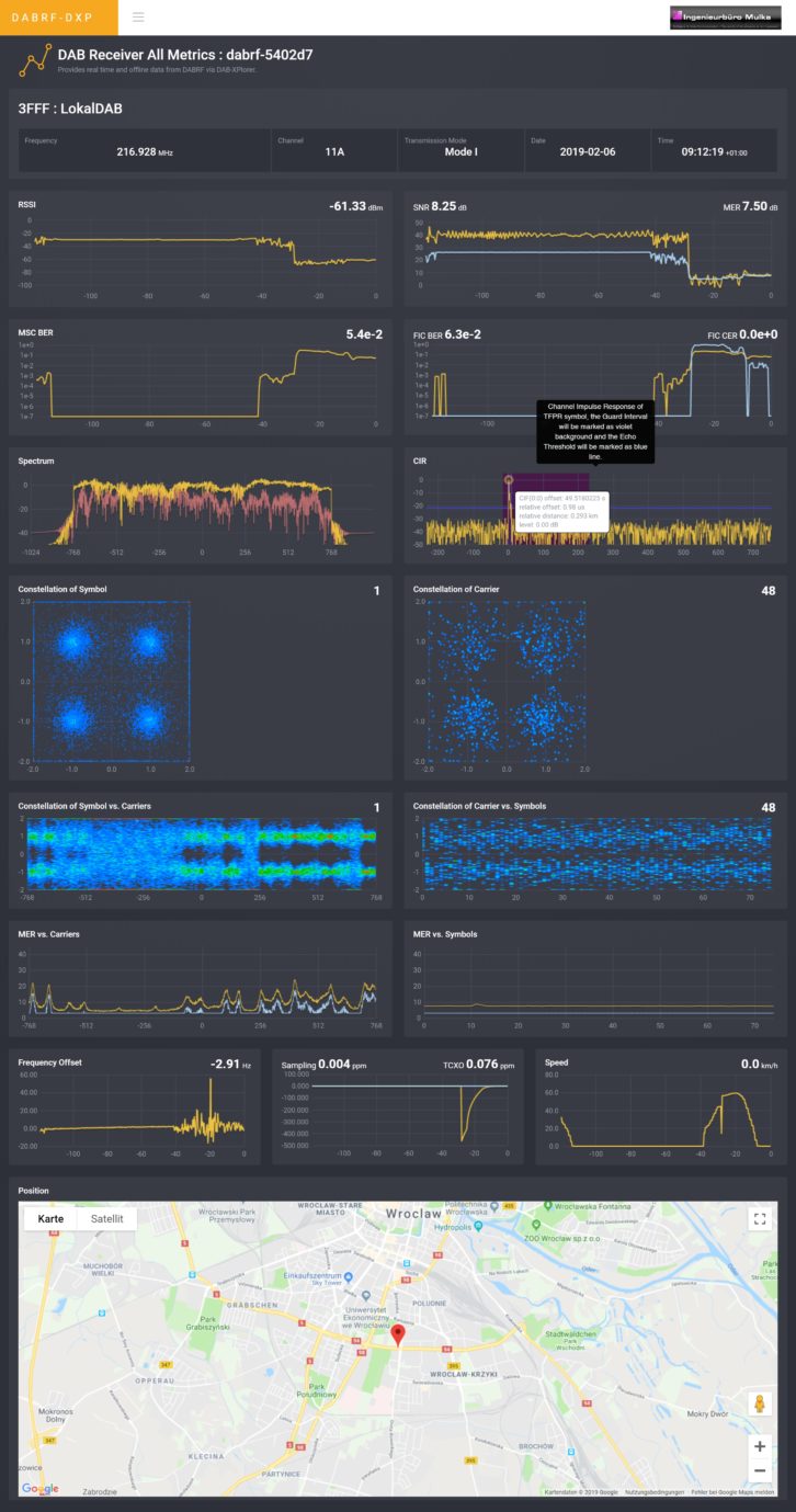
Fortunately, engineering firm Ingenieurbüro Mulka of Dresden, Germany helped us find and resolve the problem. Its DABRF DAB signal recorder, player and analyzer allowed us to monitor recorded EDI files. This included embedded metrics (RF level, SNR and MER, bit error rate before Viterbi for MSC and FIC, FIB CRC error rate, in-band spectrum, channel impulse response, relative time position of null symbol to GPS, constellation diagrams, MER diagrams, frequency and sampling rate offset, GPS coordinates and time).
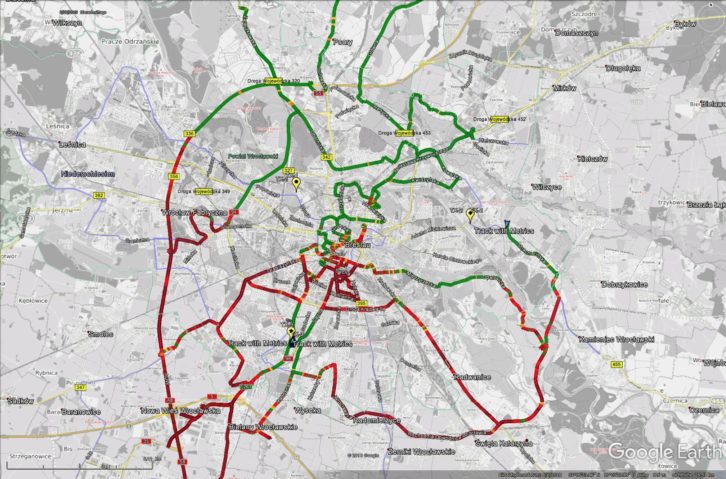
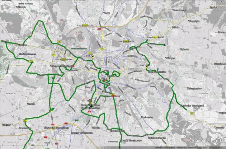
Using the monitoring tool and very sophisticated software for local DAB signal analyzing, we drove more than 600 km and recorded gigabytes of EDI files to measure the SFN coverage. A good indicator for the quality valuation is the FIB-CRC error rate, which was plotted over the map (green represents no CRC errors, red signifies high CRC error ratio.
Fig. 2 shows no reception in the city center, even though weinitially expected the best results in that location and from an SFN when all three transmitters are in sync. The locations of the transmitters marked with the location icon are as follows:
- Transmitter number one: Wroclaw University of Science and Technology: 51.1271491,17.0091166
- Transmitter number two: The National Institute of Telecommunications: 51.1153582,17.1135315
- Transmitter number three: Radio Wroclaw: 51.0708741,17.0061065
THE SOLUTION
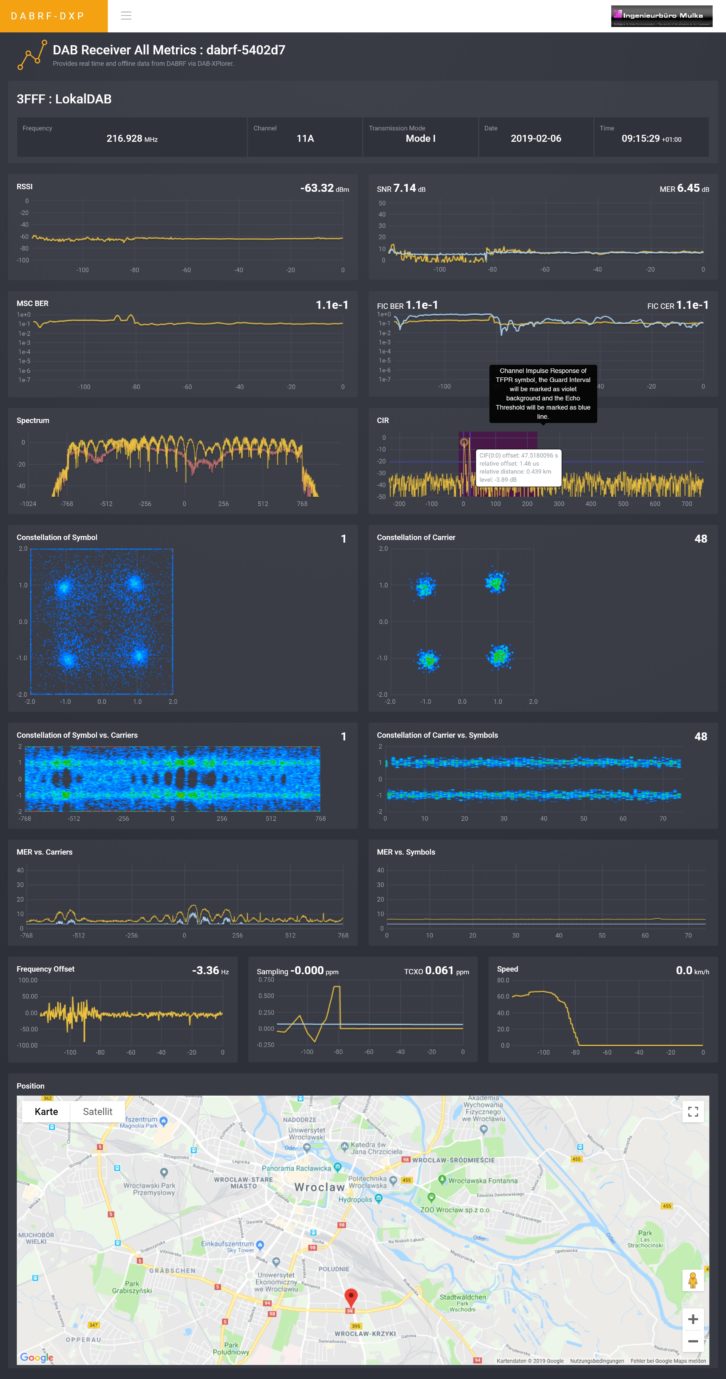
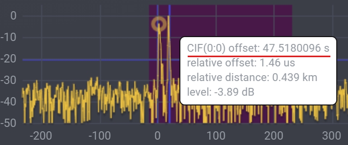
We replayed the recorded EDI file in the laboratory and analyzed the metrics. An interesting point is the low SNR at good RF levels at some critical places. Figs. 3 and 4 illustrate the findings.
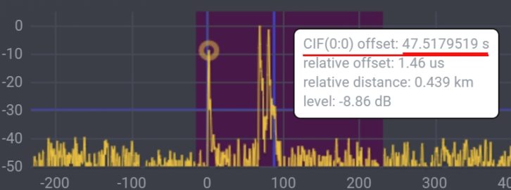
In both cases, the RF level is around -62 dBm, which is high enough for a good reception, but the SNR is 8 dB, which is very low. The reason is that transmitter number 3 had an unexpected delay of around 2 seconds, which was measured by the DABRF in the diagram of the Channel Impulse Response (Figs. 5 and 6).
The decisive factor for time measurement is, that a reference between the time and the frame is made with CIF counter (0:0). This is a unique feature of the DABRF receiver.
[Read: Umbria Welcomes New DAB+ MUX]
We discovered that the problem was caused by the wrong address on the DNS server in transmitter number three, which in turn caused a problem with the transmission of the corresponding NTP data, resulting in the lack of synchronization.
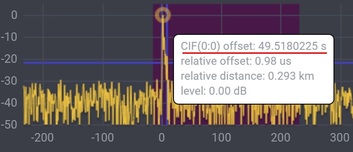
After correcting the time synchronization of transmitter number three, the SFN works as expected. Figs. 7 and 8 show the result.
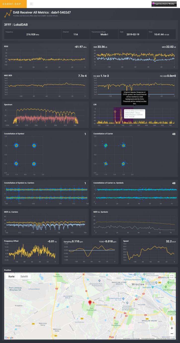
Now, the RF level is at about the same level as before (– 62 dB), but SNR is higher than 33 dB and that ensures perfect reception.
CIF (0:0) offset is now the same for all three transmitters. This is visible in Fig. 9, which illustrates the channel impulse response where all three transmitters, seen as three yellow peaks, work within the guard interval of 246µs represented with a violet background.
After discovering the cause and overcoming this serious synchronization problem, members of the project team are now able to focus on promoting the solutions they have created for local and small broadcasters.
They are now sure to be able to provide a quality signal and coverage that will allow the quality distribution of a wide range of DAB+ services to their audience.