One common desire for broadcasters is to extend coverage. That isn’t always a practical thing to do — but having your coverage optimized within your allotted coverage area is a realistic goal.
The idea of the single-frequency network is nothing new and has been implemented in both the AM and FM bands. Interestingly, DTS’ HD Radio system lends itself readily to SFN implementations.
In the November 2015 issue of Radio, we published an article entitled “iHeartMedia Gets Valley Coverage With Santa Clarita Booster.” As one might expect, there are other boosters located at the same spot, serving the same purpose.
In this article, we’re going to look at the booster built by the University of Southern California’s KUSC. (The booster operates in hybrid mode, but in this article we’re focusing on the design of the digital transmission.)
Santa Clarita is an amalgam of five smaller towns, making up a fairly large bedroom community located about 30 miles northwest of downtown Los Angeles and within L.A. County. It’s an ideal location for a SFN system because, to a very large extent, signals from Mt. Wilson and Mt. Harvard, the primary FM and TV transmitter sites for L.A., are shadowed there.
RESEARCH
A considerable amount of research has been done in the implementation of SFNs with HD Radio. An important paper used in research for this article was written by Anders Mattsson and John Kean; read it here.
A second article of interest was published by NAB Fastroad, entitled”HD Radio Single Frequency Network Field Test Results WD2XAB Baltimore & WKLB Boston.” Both make for great reading, should you want to learn more about the topic.
For additional research, I spoke with Philipp Schmid, research engineer at Nautel Ltd., as well as John Kean and Ron Thompson, the chief engineer of KUSC.
As I mentioned earlier, HD Radio (as well as DAB and DRM) can both be used successfully in the construction of SFNs.
According to Anders Mattsson (mentioned in the article to which I referred early), digital radio in general has a distinct advantage, not so much in the transmission mode, but in the design of the receivers: “This poor performance (of analog SFNs) is not due to any inherent limitation in SFNs. In fact, it is because of the lack of [RF] equalizers in traditional FM receivers. At the moment the receiver can handle the multipath, SFNs offer many potential advantages. Since all digital systems such as HD Radio and DRM already have equalization, the old limitations are gone.”
LIMITATIONS
Even so, as one would expect, there are practical limits to what can be done with HD Radio SFNs, and they mainly relate to what is known as the guard interval in OFDM.
Recall that the IBOC transmission scheme uses Orthogonal Frequency Division Multiplexing, where parallel data streams are transmitted by way of multiple low-level carriers, themselves modulated in a standard fashion (such as QAM or QPSK). In the specific application of IBOC, hundreds of subcarriers are used; the modulation scheme is QPSK.

One of the big advantages to OFDM is its robustness, and that is in part attributable to a long symbol length. Symbol length is the amount time that the individual carriers are in a state that is detected by the receiver. Part of the symbol length, though, is called the guard interval. This is the amount of time that needs to elapse prior to the next symbol. In other words, there is not a continual flow of symbols; between changes, a certain amount of time expires — the guard interval.
This is important because of the mitigation of multipath on the receiver end. If the receiver, in the field, encounters two IBOC signals that are on the same frequency, with synchronized data, there are two characteristics that will determine whether or not there is a destructive multipath effect:
- One signal is considerably stronger than the other in which case the weaker signal doesn’t have any effect on the receivers detection of the subcarrier state changes on the stronger signal, or
- Both signals are of nearly the same strength, and they are delayed by some amount of time because of different distances between the receiver and the various sources.
If the time differential between two arriving signals is within the guard interval, the receiver can correlate the symbol changes in both received signals, and essentially they add. If the delay is outside (or longer) than the guard interval, then the picture gets blurry; the symbol changes are too far apart, and intersymbol interference is caused.
For HD Radio the symbol length is 2.9 milliseconds and the guard interval is 150.5 microseconds. This would lead to a practical limit of about 14 miles in difference between the two IBOC sources, and considering that the receiver could be located directly between the two, there would be a practical limit of about 28 miles between transmitter sites (based on 75 s).
However, the current state of the art includes the addition of a flight delay in one of the RF paths so that the OFDM carriers correlate in particular geographical areas. In the case of KUSC (as we will see) a delay was added to the transmission of the booster so that the OFDM carriers would add constructively within the geographical area that presented the lowest desired to undesired (D/U) signal ratios.
One of the two signals can slip in time, in relation to the other, by as much as half of this amount of the guard interval, and the signals will still correlate.
So just what does the ratio of desired to undesired have to be, so that the effects of ISI are minimized?
I went to Philipp Schmid for an answer. He compiled the data, seen in Fig. 1, which shows that as the time difference between the two signals gets shorter that the D/U ratio can be less for a given BER.

Fig. 1 shows that as the time difference between the two signals gets shorter that the D/U ratio can be less for a given BER. The 2 ms delay line on the graph was an outlier I asked Schmid about.
“At 2ms offset, you essentially have an uncorrelated signal. The other signal effectively is noise to the desired signal. It works so well because IBOC is very robust,” he said.
“Look at John Kean’s 2008 paper, ‘An Improved Coverage Prediction Method for HD Radio,’ Fig. 4. You can see for steady state you only need 4 dB D/U that matches the reception cross over point in my plot; in a mobile environment you may need 7 dB, which I did not test… you only need about 4 dB to the noise floor to have HD lock. FM needs about 20 dB for comparison.”
SYNCHRONIZING THE SFN DATA
Recall earlier we spoke of the correlation of synchronized data from two sources of OFDM carriers. These two sources are the main transmitter, and the booster transmitter. A large part of the success of the KUSC system is attributable to the technique used to ensure the data transmitted from the two sources is in sync.
Fig. 2 shows the system configuration.

The NV-15 is the KUSC main transmitter, located at Mt. Harvard; the VS300 is the booster transmitter, located at Oat Mountain. E2X packets are generated by the single exporter at Mt Harvard, and then sent via IP back to the KUSC studio, and thus cross-connected to the IP link that runs to Oat Mountain.
“KUSC has had the classic Intraplex T1/TDM shelves deployed for some time. In the case of this project, we just wanted to be able to continue to use what was available to us without having to revamp the whole STL system right away. [These are shown in Fig. 2 as the back-to-back STLs with the studio in between.] The shelves are a bit older, but we were able to upgrade to the PT/PR353 uncompressed audio cards and to run the Ethernet extender card [DS-64NC] sets in the same box. Seventeen time slots for audio at 32 kHz and slots 18–24 for the Ethernet bridge which gives 448 kbps throughput. Oat Mountain has the same Intraplex shelf units provisioned exactly the same way,” said Thompson.
Nautel’s Reliable HD transport protocol is used to send the packets from Harvard to Oat.
“The packets are time stamped so that each exciter’s firmware can buffer properly to transmit the packets simultaneously and against the calculated propagation delay. [More on that follows.] Also, it allows the exporter to send the packets to two IP destinations, i.e., the main and booster exgine cards via UDP to the broadcast address 10.10.15.255 in this case since you can’t send via TCP/IP directed paths to multiple addresses. The protocol allows error correction resend requests to be initiated by either exciter over a return UDP management channel back to the exporter.”
I spoke with Schmid again to gain understanding of the synchronized nature of the data path between KUSC’s main transmitter at Mt. Harvard and the booster site at Oat Mountain.
“One way to ensure time synchronous arrival of signals over the air is to fix the throughput delay of the entire signal chain from the common point at the single exporter at the studio or main transmitter [as is done in this particular case] to the RF output on each transmitter in the network,” said Schmid. “This could involve any number link configurations in between that could all have different delay characteristics.”
Looking at Fig. 3: Note that the first three steps occur in the exporter at Mt Harvard. The E2X packets are forwarded back to Oat (through the process described earlier) one second after the audio within the E2X packets had been sampled and a SYNC time tag (counting the number of 10 MHz cycles after the last 1 PPS) is inserted. The exporter literally waits and holds the packet before sending it across the STL. Packets can then take up to an entire second to traverse whatever STL combination is in use. At the transmitter site, the exgine modulator holds on to any received packets until 1 second from when it was sent by the exporter based on the “SYNC” time tag in the E2X packet itself. The exgine modulator is then allowed 1 second to turn the E2X packet into modulated symbols that are then precisely released on the next second, 3 seconds after the audio has been sampled at the exporter based on the embedded SYNC timetag. Use of the GPS receivers 1 PPS signal allows both ends to work in lock-step with one another.

“Using this method… we can ensure two geographically separated transmitters can produce IBOC within 1-2 us of each other,” said Schmid.
FLIGHT DELAYS
Let’s participate in a small thought experiment here. Imagine yourself standing on the ground, straddling a line between the KUSC main transmitter and the KUSC booster at Oat Mountain. Recall that I wrote the OFDM carriers would correlate assuming the delay between the two, as perceived by a receiver that you are carrying, was less than the guard interval between symbols. In the case of KUSC, it turns out the interference zone is physically closer to the Oat Mountain site than it is to the Mt. Harvard site.
It’s in this interference zone that the difference in time between reception of the main, and the booster, must be manipulated. (Refer back to Fig. 1 as needed.)
Since the zone is closer to Oat, some amount of flight delay is introduced there, so that the symbols as detected by your receiver match up in time; in other words, if you are standing in the interference zone, this allows signals from Mt Harvard to essentially catch up.
“A per-transmitter delay can be introduced such as to account for the signal flight time into the interference zone,” said Schmid. “With the help of John Kean, who prepared coverage simulations for us, we added 176’s delay to the KUSC booster transmission, such that the two wave fronts met 20s or about 6 km ahead of the booster. From lab experiments, we found that any time differential less than 40s will guarantee HD signal lock no matter what the d/u ratios and is expected to hold in mobile environments. This provided a safe zone of up to 12 km out from the booster and a cone behind it with where this requirement could be guaranteed. Outside of this zone, momentary HD drops could be expected but receivers can quickly re-acquire lock until a time differential of about 75s.”
RESULTS
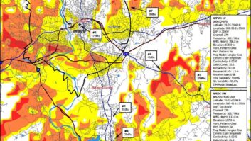
Fig. 4 gives you somewhat of an idea of the challenges for FM reception in the Santa Clarita area, situated mainly in the “V” between highways 5 and 14. Oat Mountain is just west of the highways 5 and 14 interchange. Mt Harvard is located south and east of this area, shadowed from Santa Clarita by the Verdugos as well as the ridge just north of Sylmar.

Reception testing carried out by KUSC staff found that the HD booster provides solid coverage of the Santa Clarita valley and along highway 14.
“HD is locked even with severe FM impairments. Intermittent drops only with expected terrain shield in canyons.”
It should be noted that KUSC’s HD ERP along this bearing is about 2 watts.
Sylmar is a town south and west of the mountains that impede coverage in to Santa Clarita, and has some visibility of Mt. Harvard as well. “Only short intermittent drops in the Sylmar region only with clear obstructions like underpasses, with little signal from either transmitter.”
The HD Radio SFN network built by KUSC is successful, and “it all started with just the simple thought of replacing our booster and then it grew from there when Nautel reached out with the idea of participating in the R&D project,” said Thompson.
“A digital-only booster is far more workable than a hybrid booster, but a design issue is the potential for interference to the analog FM reception at locations nearer to the booster. This effect will vary with different receivers and with each field case, of course,” said Kean.
“I can see HD SFNs taking off for all-digital when we can leave the shackles of FM transmission behind or perhaps delegate the FM to true fallback status. Statewide or perhaps nationwide SFNs could be a possibility. Cover roadways with a string of small scale HD SFN transmitters. I can see micro HD boosters in downtown cores, tunnels and buildings (underground parking). This would be a radical shift in RF planning but may provide better spectral efficiency and better signals for the listener,’ said Schmid.
The difficulties in building successful analog FM boosters are numerous and well documented. I find it interesting, and hopeful, that as the importance of digital transmission increases over time, SFNs can play a part in maximizing our reach and overcoming reception issues that are inherent with analog FM.
I would like to thank Philipp Schmid of Nautel, Ron Thompson of KUSC and John Kean for their assistance in the preparation of this article.