Present-day transmitters practically can repair themselves, with all their diagnostics. But if you have an older tube transmitter, repairs can take time.
There are two main reasons. First, the original manufacturer may no longer support that model; second, you may be missing the instruction manual and schematics. Older transmitter documentation can be found on the Web, but another source is an older engineer who may have cut his teeth on these rigs. Check with local contract engineers, as they need to have knowledge on a variety of models and power levels.
Whenever the transmitter fails, it’s important to consider all evidence obtained by meters, tripped breakers or burned components. This is a good reason to visit your sites regularly. If the transmitter has a blower fan, is it running? Is it making noise? The absence of normal sounds, like that blower motor, or the clack of relays and contactors when restarting the rig, can help you diagnose where the problem is.

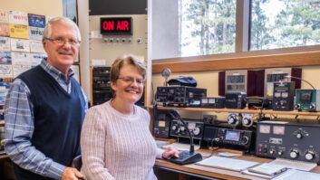
Fig. 1: Can anyone claim this station studio? When troubleshooting, take someone with you. In a contract situation, I’d ask the GM, owner or PD to accompany me. We all know what kind of respect is earned when the plate ON switch is greeted by flames shooting out the top of the transmitter and accompanied by a terrific bang. Engineers have told me they prefer to restart their rigs using their cell phone dialed into the remote control — so they’re not right next to the fireworks.
In working on a particularly troublesome Collins Power Rock, we’d often use a wooden broom pole to push the ON button, just so we weren’t right on top of the rig when it exploded.
If you’re new to the industry, understand that this is dangerous stuff. No station is worth dying over. Some straightforward safety steps are in order.
To begin: Never work on a transmitter when you are tired. And its corollary: Never work alone. Should something happen, you want someone to be there who can call 911.
Most transmitters are controlled by remote control systems. Make sure the remote control is disabled or in maintenance mode, so no one back at the studio accidentally turns the transmitter on while you’re inside it.
Then we get to the AC breakers. It’s important that all are identified, and turned off. Again, this is so you can make your internal inspection safely.
As you open the back, check that the power supply shorting interlocks, as well as the control interlocks. They should be working. What you want to inspect is that the interlock wiring is intact. Sometimes engineers will defeat the interlock switch with a clip lead and forget to remove it. Before reaching inside, take the shorting stick and short out all components.
If your transmitter doesn’t have a shorting stick, construct one. I’ve seen folks use a yardstick or broom handle about three feet long — nothing fancy. Screw a bolt into one end and sandwich the ground cable lug between two nuts. At the other end of the ground cable, affix a large spring clamp — like an oversized alligator clip. The ground clip is attached to the transmitter chassis, and the business end of the shorting stick is used to touch all components. This ensures they are de-energized.
The first time you encounter a live component and hear the crack and see the arc, just remember that could have been your hand! Safety components, like interlocks, are supposed to keep you safe. The shorting stick is akin to wearing a belt and suspenders. Working around gear like this, one can never be too safe.
Keep your camera-phone handy to snap pictures of anything suspicious. Use your nose, as well as your eyes, to spot burned or overheated components. A bright trouble lamp is a must-have, and your big box hardware stores have LED versions that won’t burn out. If you are using a traditional trouble lamp, the next time your tower lights are changed, tell the rigger to give you the old bulbs. This is a neat way to recycle the side light bulbs, as they certainly will enlighten the subject.
Let’s say nothing obvious is visible. Button things up, turn the breakers on and try again to bring the transmitter up. Before touching any controls on the transmitter other than PLATE ON, grab a pad and a pen, and write down what you see. Are overload lights lit? These indicators will point you to the section of the transmitter that’s at fault.
Does the transmitter come on but quickly shut down? That’s usually a sign of a short somewhere. What do the meters read? If there is no indication of plate voltage, suspect the high-voltage power supply (HVPS).
Check the filament voltage meter — no filament voltage means no tube emission. Depending on the environment, I’ve seen the leads to the tube filaments corrode. These cables carry a lot of current, that’s why they are the diameter of your finger. Clean, tight connections are imperative.
This is just a start, and we’ll continue in future columns. Some of our sage readers will have other things to check, and we’ll include them.
****
Bruce Roberts is the director of engineering for Apex Broadcasting in Charleston, S.C. Bruce shares a picture of a station he thinks was near New Albany, Miss., shown in Fig. 1. He inferred the location from the poster hanging on the wall.
This was typical of small market stations in the ’50s and ’60s. A very low-budget build, and the equipment just lasted forever. Bruce wonders if Workbench readers can identify the specific station, and share any stories.
He concludes by pointing out those turntable remote start switches down where your left knee would be … gee, they look like light switches! Surprise, they are!
Email your thoughts (and high resolution pictures) to [email protected].
Contribute to Workbench. You’ll help your fellow engineers and qualify for SBE recertification credit. Send Workbench tips to [email protected]. Fax to (603) 472-4944.
Author John Bisset has spent 45 years in the broadcasting industry and is still learning. He handles West Coast sales for the Telos Alliance. He is SBE Certified and is a past recipient of the SBE’s Educator of the Year Award.


