I was part of a conversation recently with Workbench contributor Paul Sagi and equipment inventor and manufacturer Harold Hallikainen.
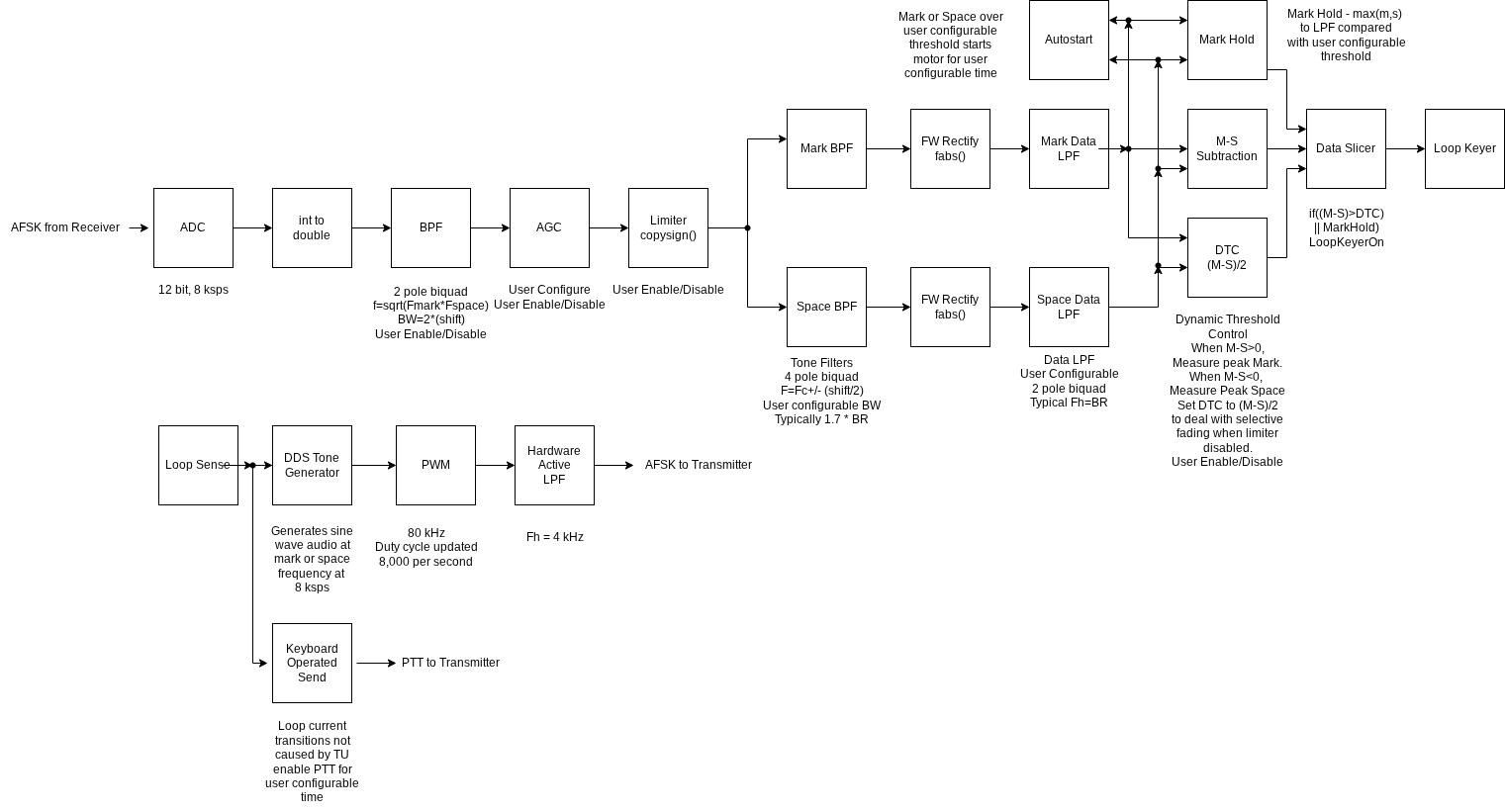
Paul shared a free download for diagramming, draw.io. This tool works with Google Drive and Google Workplace. According to its website, “draw.io is a technology stack for building diagramming applications, and the world’s most widely used browser-based end-user diagramming software.” Harold has used it to create useful block diagrams.
Have you used this tool, or something similar? Share your experiences. Drop me an email to [email protected].
Intermittent operation
Archie Simpson’s tale about using “impact engineering” to fix an intermittent in an audio console brought a lot of chuckles.
Fred Baumgartner reminds us that when someone drops a handheld radio from a tower, we might say the radio has been “returned to kit form.”
Meanwhile contributor Frank Hertel offered an anecdote about intermittent operation. In the late 1960s, he worked for a TV station that had an RCA quad tape machine with a problematic module. The module used Blue Ribbon Connectors — big, heavy-duty plastic connectors with gold spring fingers. The contacts were rated for high current flow.
Years later, Harold Bass of relay manufacturer Potter & Brumfield told Frank: “If you have too large a contact, and do not flow enough current through the contact, it will likely eventually fail to provide a good connection. This is also true of relay contacts.”
Frank experienced a similar phenomenon while maintaining a Harris SX-1 AM transmitter. At sign-on, the transmitter would perform the first “step” of its step-start procedure but would not step to the full power setting. Frank thought it needed a new controller board.
Harris support folks suspected a dirty contact on the large contactor in the bottom of the main breaker panel. The tech further explained that one set of the contacts on that main contactor was used to send a verification signal to the controller board. At the time, engineers didn’t know that they were not drawing enough current through those spare main breaker contacts to keep them “clean,” so to speak.
Frank cleaned the contacts that the small wires were connected to, and the problem was resolved.
Touchy feely
In a recent column I recommended that when you’re inspecting a transmitter site, open the breaker panels to check whether any breakers have tripped.
Scott Cason, based in Louisville, Ky., has been a broadcast engineer for 35 years and a contract engineer for 21. He’s also an ABIP inspector in Kentucky and Indiana and the director of engineering for the Kentucky Broadcasters Association.
He recommends that you feel the front of each breaker with your hand to see if any are warmer than normal. If you do this regularly, you’ll know which ones run a little warm. Any breakers that seem warmer than they usually do could be sending a red flag. (And you know a failure would happen on a weekend or over a holiday.)
Also, if you have the budget, Scott suggests going a step further by investing in an infrared thermometer.
Clever!
I mentioned Harold Hallikainen above, and you may recall me telling you in a previous column about his use of engraved panels.

Harold sends along images of an interface panel used between a remote control system and the transmitters at an FM station. The panel is shown in Fig. 2. It was all wire-wrapped relays, as seen in Fig. 3.

The relays are socket-mounted on panels held by spacers on the back of the panel. The spacers on one side are hinged so the back panels can be “folded” to the side for access, shown in Fig. 4.

Notice that the back of the engraved panel is engraved with the reverse image of the front. This made it easier to determine which front-panel part you’re working on.
Speaking of Harold (W6IWI), if you are a ham, you will enjoy his website.
Share your ideas (and qualify for SBE recertification credit)? Email Workbench tips to [email protected].