Wayne Eckert is an engineer with the Rural Florida Communications Cooperative. He occasionally comments here in Workbench on electrical matters of interest to broadcast engineers.
He noted the article by Mark Persons in the Oct. 14 issue of Radio World detailing lightning damage at KRJM. For engineers who are interested, he points out that AT&T has a relevant document “Grounding and Bonding for Network Facilities” that can be downloaded free in PDF form.
Wayne writes that while the document was created for central office grounding and bonding, it is now considered a company reference for all cell sites as well. And many parts it are applicable to broadcast sites, studios or any other facility where uptime is of high importance.
Wayne believes that if just some of the practices detailed in the AT&T document had been applied at KRJM, the damage suffered could have been greatly reduced.
One thing that caught Wayne’s eye was it appears that the pole supporting the STL link lacked a down ground. Wayne bases this opinion on the damage to the pole and from what Wayne could see in the photograph.
A down ground is an old utility practice and is a simple lightning protection device. Normally before the pole is placed, a lineman will secure a #6 hard drawn copper conductor to the pole with fencing staples. This line will attach from the top of the pole to the “butt” or bottom of the pole, leaving 6 inches or so of it standing above the top and coil up a few feet of the cable on the butt.
The goal is to produce a grounding electrode on the butt of the pole, so when the pole is placed in the earth it will make good contact with the earth.
If the pole is already in place, you can add a down conductor by installing an 8-foot ground rod into the earth.
Note well: Before pounding anything into the earth, contact your state’s one-call utility notification center. All states have such centers and require by law that you call 48 to 72 hours before digging. In most states the number is 811.
A “locate” will be scheduled and done at no charge to determine if there are any underground utilities present. Keep in mind that though this service is free, it is not “next day,” so plan your work, giving the “locates” folks plenty of time. Failing to notify them can get you killed should you drive the ground rod through an electrical cable or natural gas pipe. At the least, it can result in being sent a substantial bill from a utility should you damage something below grade.
The down conductor provides a bypass for the lightning’s energy into the earth, sparing the pole from extensive damage. Keep in mind that all pole attachments shall be bonded to the down ground cable. It is required by code that you bond the grounding electrode to the building’s grounding system using a direct buried #6 copper conductor, which prevents potential differences between grounds.
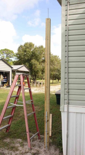
Wayne included several photographs that detail a down ground installed on a pressure treated 4-by-4 support pole.
In Fig. 1 above, note how the down ground is stapled to the support post. Also note that the last 36 inches or so of the down ground cable is protected by a piece of PVC pipe secured to the post.
Since the size of the 4×4 is too small for a butt coil, a ground rod was used, shown in Fig. 2.
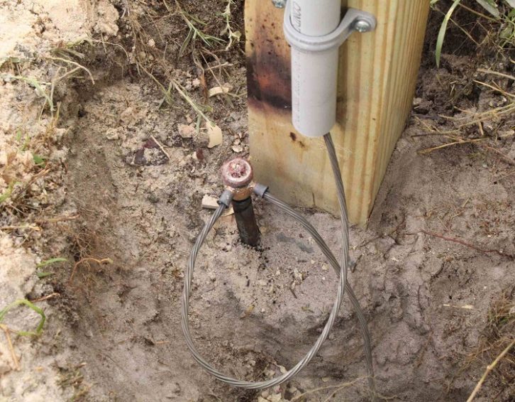
In this photo, also note that all of the bends in the grounding conductors are sweeps (gentle curves, no sharp angles). This is very important as it minimizes the inductance in the grounding conductors.
Wayne writes that though lightning is direct current, it acts more like RF due to its extremely fast rise time, so inductance must be kept to a minimum.
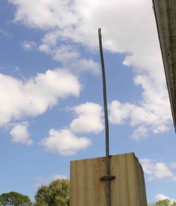
Fig. 3 shows the top of the 4×4 pole with a pigtail, to which supporting structures like antennas or STL dishes can be bonded and grounded.
More on GDTs and MOVs
Robert LaJeunesse in Ann Arbor, Mich., holds an MSEE. He read with interest our discussions about gas discharge tubes and metal oxide varistors.
Bob points out that there are unique differences. The MOV clamps above its breakdown voltage while the GDT clamps below its breakdown voltage.
This may seem like a minor point but it has a major impact on the power dissipated by the clamping device, not to mention the pass-through energy.
With the GDT clamping lower, this device reduces the amount of energy that can pass into the subsequent protected circuitry; and the lower clamping voltage likely allows for more clamping current without over-dissipating.
It also makes sense that both be used together to protect a load. The MOV would absorb lower power surges but might allow the voltage to rise significantly above the MOV threshold on a higher current surge. The GDT can then kick in and clamp the voltage down, pushing more of the dissipated power back to the source — and source wiring — thus limiting the surge power that gets to the protected device.
Bob notes two PDF resources from Littelfuse to learn more. One is “Varistor Products Overview.” The other is a datasheet about its CG6 gas discharge tubes.
John Bisset has spent more than 50 years in the broadcasting industry. With this column he begins his 31st year writing Workbench. He handles western U.S. radio sales for the Telos Alliance. John holds CPBE certification with the Society of Broadcast Engineers. He is also a past recipient of the SBE’s Educator of the Year Award. Workbench submissions are encouraged, qualify for SBE Recertification and can be emailed to [email protected].