Thanks for your comments on the super-bright tri-panel LED light “bulb” described in the last column.
Workbench contributor Frank Hertel of Newman-Kees RF Measurements and Engineering described another approach to lighting your shop or workbench with LED bulbs — and this one is dimmable.
The dimmer selector means you won’t blind yourself with overly bright light unless you need to.
What started it
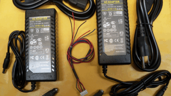
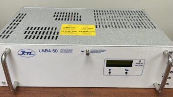
Frank needed to replace spot and floodlights on his tractor, and found the LED fixtures shown in the first two photos on the internet.
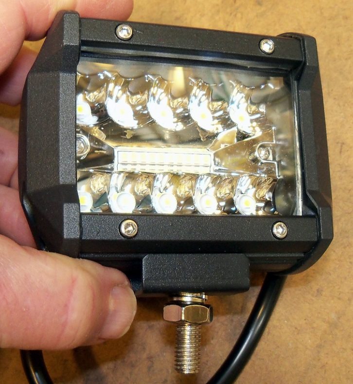
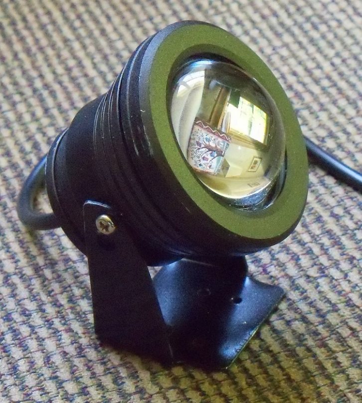
Before installing them on the tractor, he tested them on the workbench. Frank was impressed with how much light both fixtures provided, exceeding the brightness of his more expensive 120V LED shop lamps.
However Frank felt there might be cases where the brightness was too much for the work at hand, so he decided to build a dimmer circuit.
In selecting a method of dimming the LED fixtures, Frank first considered the simplest method: varying the DC voltage. This will work, but because of the “avalanche” turn-on point — it’s not a smooth ramp-up or down — varying the DC voltage makes for a sloppy dimming control.
Enter the 555
Frank decided on the ever-so-handy 555 Timer IC, which was configured as an adjustable duty cycle square wave generator.
Seen in the accompanying schematic, the 555 square wave generator drives an MPF102 FET, which in turn drives a D718 power transistor that provides a “pulsed” 12V variable duty cycle driving the LED lamp fixture.
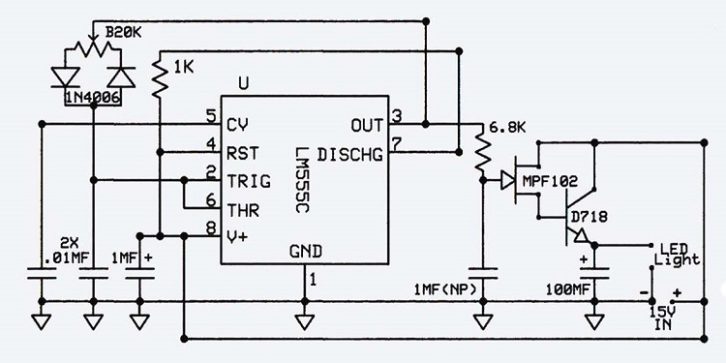
The fixture is only pulsed long enough with the 12 volts to establish the desired brightness level. This method overrides the “avalanche” “on-off” effect that is noticed when a variable voltage is used to attempt control of the fixture’s brightness.
Stated another way, the LED fixture’s brightness can be viewed in relation to the length of time the 12V pulse is present. Therefore, the duty cycle of the 555 IC’s square wave is the determining factor for the LED fixture’s brightness. Pretty slick!
He used a widely available and inexpensive D718 power transistor that is rated for 8A at 120V. With a properly sized 15VDC supply and heatsink for the D718, you could power several LED fixtures with just one dimmer. Alternately, the circuit is small enough that you could mount several dimmers in one chassis, for individual control.
Frank realizes you can buy a pre-made dimmer but asked, “What fun is that?”
Besides, this dimmer circuit can handle a lot of current and is small enough that multiple dimmer circuits can be mounted inside one chassis.
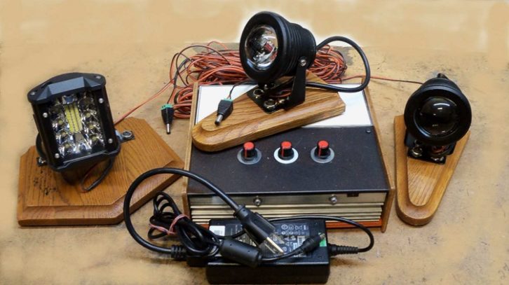
After outfitting his tractor, Frank mounted three fixtures on wood pedestals so he could focus the light on what needed illuminating. Frank adds that if pointed at a white ceiling, the fixtures provide ample room illumination.
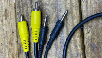
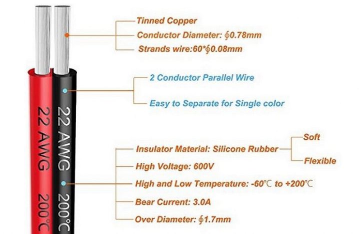
The completed project provides for three individually dimmed LED fixtures. You’ll note in the photo that Frank chose silicone jacketed wire to connect the fixtures to the dimmer. This wire is super-flexible, albeit expensive. The silicone helps avoid tangles. The 22 gauge wire had an almost immeasurable voltage drop over the 30 foot length that Frank chose.
Parts are listed at the end of this article. Keep in mind that when selecting the working voltage of the capacitors, good engineering practice dictates choosing a capacitor rated at twice the supply voltage. Since we’re talking about 15VDC in this circuit, choose capacitors rated at either 30 or 50 Working Volts DC (WVDC).
PS: If you’ve made it this far, you are definitely an engineer who likes to build and tinker. San Diego’s Marc Mann reminded me of a site that will occupy your interest for hours with the variety of parts for sale. It’s Marlin P. Jones and Associates at www.mpja.com. Their online catalog is fascinating, and the site features bargains and closeouts. You can sign up there for an email flier or access their online catalog.
John Bisset, CPBE, has spent more than 50 years in broadcasting and is in his 31st year writing Workbench. He handles western U.S. radio sales for the Telos Alliance. He is a past recipient of the SBE’s Educator of the Year Award. Shed a little light by sharing share your own Workbench submissions, which qualify for SBE recertification. Email [email protected].
Dimmer Project Parts List
1 each 20K Pot (linear) (B20K or 20KB)
1 each 1k 1/4W Resistor
1 each 6.8k 1/4W Resistor
2 each 0.01MFD Capacitors
1 each 1MFD Electrolytic Capacitor
1 each 1MFD non-polarized Capacitor
1 each 100MFD Electrolytic Capacitor
2 each 1N4006 Diodes (non critical)
1 each MPF102 F.E.T.
1 each D718 NPN Power Transistor
1 each Heatsink for above transistor
1 each 15VDC Power Supply, sized for LED fixture demands
1 each Enclosure of your choice
1 each Knob for pot
1 each perf board and hookup wire