Dan Gunter is principal of Alabama Broadcast Services LLC, a contract engineering firm headquartered in LaFayette, Ala. He saw a presentation that I did for the Alabama Broadcasters Association’s Engineering Academy in which I discussed infrared cameras made by FLIR.
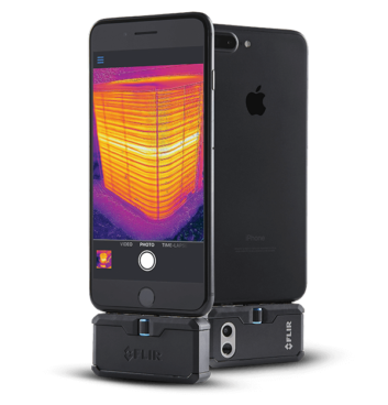
Last year, Dan bought a model that plugs into his smartphone. He says it has more than paid for itself. (The FLIR One Pro costs about $400.)
Here’s what Dan wanted to share with Workbench readers. He was at a client site to check a Harris SX-5A AM transmitter that had repeatedly blown the silver-mica capacitor in the output third harmonic filter section. Those cost about $800 apiece.
Dan got the FLIR camera ready so he could quickly shut down the SX-5A, open the rear door and grab an IR temperature reading to see how hot the capacitor was getting. He attached the infrared camera to his phone and activated the app so he was seeing real-time IR imaging.
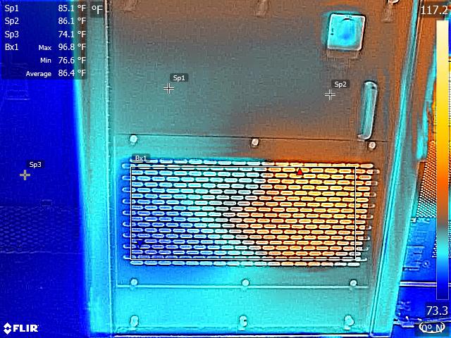
But in getting ready to inspect that transmitter, Dan happened to sweep the camera over the rear door of another rig, a BE AM5E, and discovered a potentially serious problem there. He saw a “hot spot” in the image indicating much higher temperatures at one of the twin cooling fans at the bottom of the BE transmitter’s rear door.
Measured with the FLIR One Pro, with a measurement “box” as defined in the FLIR PC software (Fig. 2), he saw that the cabinet over the blown fan was as hot as 96.8 degrees Fahrenheit, while the temperature was only 76.6 degrees in the area of the working fan.
Because these fans are behind a metallic filter in a recessed area of the door, they’re normally out of sight. And you would not see them in operation if you opened the rear door of the transmitter’s cabinet because, for obvious reasons, the transmitter must be powered down first (or the interlocks will shut it down for you).
Dan notes that this AM5E had a history of repeatedly blowing PA modules. The latest suffered a major burnout that charred the components beyond recognition on about a third of the circuit board, even melting the casing off a relay. That repair cost around $1,500.
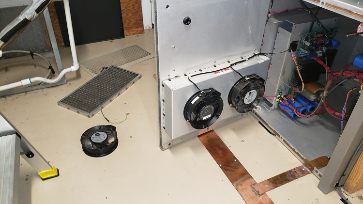
So Dan began to investigate. He discovered that the “hot” fan was not running. In fact, he had to take a hammer and reshape the perforated metal portion of the door where the fan mounts, because it was pressing against the center of the rotating fan blade/spindle. This had apparently caused the fan to burn out. In looking at Fig. 3, the suspect fan is to the left, just above the copper strap.
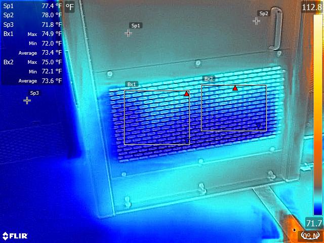
Before and after replacing the burned-out fan, Dan used the FLIR camera to measure the temperature of the transmitter’s cabinet. By replacing the fan, he decreased the temperature of the cabinet by around 15 degrees Fahrenheit in the areas adjacent to and above the PA modules. Dan suspects that the actual temperature of the PA modules and of the area inside the transmitter dropped by that much and more.
When he places his hand on the transmitter cabinet, it now feels to be at or very close to room temperature instead of noticeably warmer than ambient room air. The temperatures were notably different after replacement of the fan and resolving the fan motor binding issue, as seen in Fig. 4.
All this to say that Dan now makes it a habit to “scan” his transmitters, especially in the areas of air exhaust, intake and fans in order to spot problems such as blown fans or blocked air flow.
In the case of transmitters and transmitter rooms with lots of noise (I bet you’ve never encountered such a problem!), IR imaging can catch a lot of things that would otherwise be almost undetectable until the transmitter goes down.
We’ll tell you next time how his repair to the first transmitter turned out. Dan also said he is looking forward to producing more “how to” and technical videos on YouTube after a brief hiatus. We look forward to them.
Flashback
Last weekend I came across a YouTube video of The Seekers, in the Abbey Road studio, apparently recording their song “I’ll Never Find Another You” in 1964 (“There’s a new world somewhere, they call the Promised Land …”)
Posted by Rich963, it’s a pretty neat video featuring 1960s recording technology, though I noticed that the console VU meters weren’t moving for part of the video even as the group sang! A nice job of lip synching. Nonetheless it’s a fun peek inside a music recording studio of nearly 60 years ago.
As you watch, there’s one other apparent “flaw.” See if you can pick it up as you view the video.
John Bisset has spent over 50 years in the broadcasting industry and is in his 31st year writing Workbench. He handles western U.S. radio sales for the Telos Alliance. John holds CPBE certification with the Society of Broadcast Engineers and is a past recipient of the SBE’s Educator of the Year Award. Workbench submissions are encouraged, qualify for SBE Recertification, and can be emailed to [email protected].