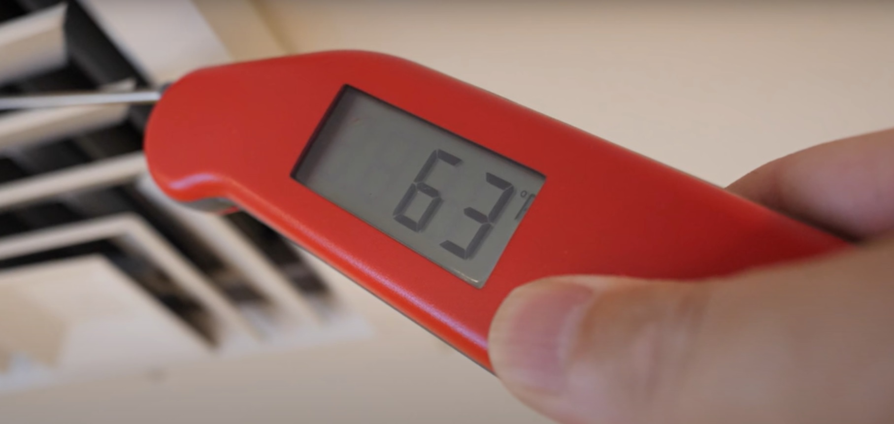
How are your studio and transmitter site air conditioning systems running?
For the majority of our readers, this is the season when reliable operations are crucial. But maybe your management has cut your service contracts to meet reduced operating budgets. If so, there’s a YouTube video that can help. It describes three steps you can take to ensure good cooling.
The first is to use a vacuum to clean the return vents of dirt and dust. Restricted air flow can hamper cooling.
The second tip is one that I’ve heard debated by engineers and air conditioning techs. The video suggests NOT using pleated high-efficiency air filters, but instead selecting the standard fiberglass ones.
The argument is about whether pleated filters restrict air flow and make a system work harder. Fiberglass filters may be fine for sites you visit regularly — like the studio — where they can be changed regularly. However, visits to transmitter sites may be several months apart. We’ve all seen the filth that the pleated air filters trap, especially in transmitters. Ask your air conditioning tech or the manufacturer of your system for a recommendation.
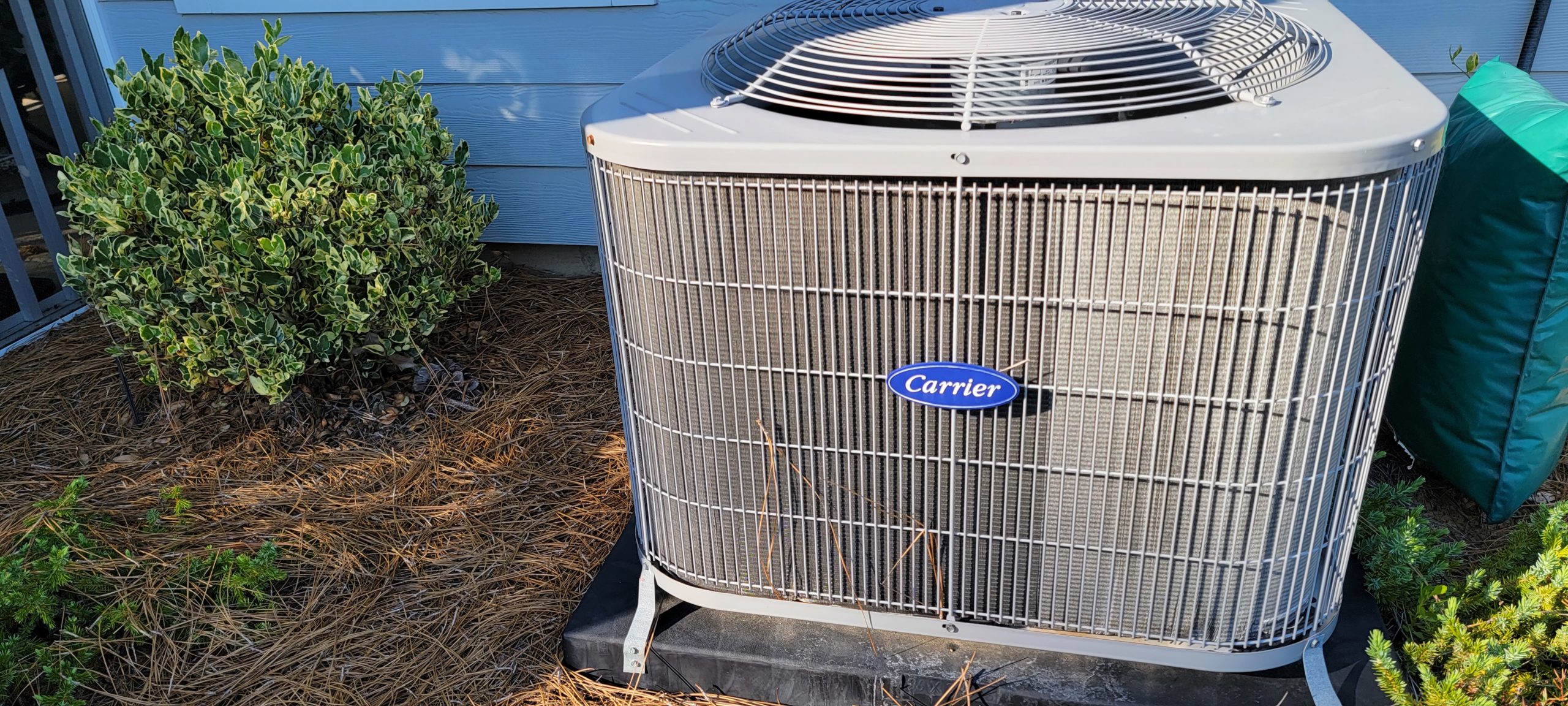
The third tip is simple enough: Clean the outside condenser unit. The fins get clogged with dirt, dust and insects as air is drawn from the front, sides and back and pulled through by the top-mounted fan.
Disconnect the AC at the condenser. Using diluted dish soap, squirt the liquid through the vents — no disassembly needed. Allow the soap mixture to sit for a few minutes, then use a garden hose to rinse the fins, cleaning the dirt-encrusted suds from the unit. Rinse several times with clean water from the garden hose, though not at high pressure lest you damage or distort the fins.
This routine provided a cooling improvement of 10 degrees in the video. Not bad for an hour’s work. Watch it here.
Mic mystery
Evan M. Tidwell is the general manager of WSHF(FM) in Muscle Shoals, Ala. (“Real Country 94.5, The Voice of the Shoals”).
Evan writes that the picture from Dan Slentz that we published in June shows an RCA 4-AA condenser mic, manufactured by General Electric.
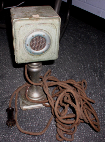
This model was introduced in 1928 to compete with Western Electric’s 47-A condenser. The RCA designation is 4-A for the mic and an extra A for the “Announce” stand. The 4-AP version shipped with the “Program” floor stand.
The mic’s multiple pins are to allow both the audio circuit to pass through the cable, as well as 6-volt and 200-volt supply voltages for the vacuum tubes.
When introduced, Evan says, this model was an impressive replacement for the carbon mics in use at the time. Many photographs of NBC and other studios from 1928 to 1933 show this microphone.
Once RCA introduced the ribbon or velocity mics in 1932, they quickly replaced most condensers.
Evan moderates the Vintage Radio Station Broadcast Gear group on Facebook, to which Workbench readers are invited. Evan welcomes readers to share photos of your favorite pieces. Remember to send them to us, too, especially if the mic is still being used!
Arizona Public Media Senior Broadcast Engineer Stephen Claasen also remembered this microphone model from a collection owned by his father, and remembers his dad identifying it as a condenser mic.
Unlike the electret condenser mics of the 1960s and later, the capacitive element needed to have an external charge on it continuously, and the output was quite low, so audio amplification was necessary. As Stephen remembers, the condenser element looked a bit like the carbon button mics, but internally it was different.
[Read Another Workbench by John Bisset]
Sniffing out AES signals
Those of us who have transitioned from the world of analog signals to AES and digital probably still remember the “Fox and Hound” signal tester.
The Fox was an audio signal generator clipped on one end of a wire, and the Hound was an inductive signal “sniffer” that identified the cable carrying that test signal.
Alan Colwell, CPBE, wrote to see if there was a piece of test equipment that can be used the same way but to identify AES signals.
System integrator Edwin Bukont, founder of E2 Technical Services and Solutions, reminded me of the Ward-Beck Bit Spitter and Bit Buddy. Sadly, they are no longer manufactured.
Ed says the next closest solution isn’t cheap. Most devices that will generate a tone or silence for AES are video products, so they are AES3id. To get AES3, you would need suitable impedance transformers; then you need something to demodulate and “hear” the signal. That solution starts at $2,000. It’s not cheap, and not always that functional either. The good stuff is in the $3,000+ range.
Ed’s best inexpensive solution is to buy StudioHub AES converters from Angry Audio and put one on each end of the circuit, coupled with a tone generator and a powered speaker.
For a single-box solution containing both a generator and a receiver, there is the Whirlwind Qbox-AES at under $700. This is an AES3/AES3id box with a built-in speaker. It does require a separate analog tone generator to be used with the AES generator, so there is some added expense.
Finally, depending upon your needs, another option may be to get a USB-AES sound card for a PC or laptop and use the free audio tone generator and edit software to generate a tone and monitor it.
Let me know if you have discovered any other solutions. Send Workbench tips to [email protected].