Ground systems
Sep 1, 2008 12:00 PM, By John Battison, P.E., technical editor, RF
Due to space limitations in the September issue, John Battison’s RF Engineering column is shown here in its entirety.
The average ground system is quiet, dependable and retiring, performing its work efficiently, without demand for attention. A properly installed and maintained ground system will usually continue to conduct space current to the transmitter’s common return until the system begins to deteriorate. Unfortunately, too many stations try to economize when installing or maintaining ground systems.
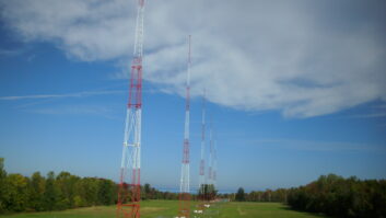
Early on, vertical radiators were the most suitable for AM broadcasting. AM operation is generally based on ground wave coverage, although skywave coverage is often desired and implemented intentionally. The single vertical dipole tower around 90 degrees in height has become a very popular AM radiator. When operated over the best achievable low-resistance ground system it is very efficient. The phrase “low-resistance ground system” is the crux of the operation with vertical radiators usually between 90 and 180 degrees high.
The most efficient operation of a vertical radiator requires mounting over a perfectly conducting plane surface. This is rarely achievable even with the use of very low loss conductors in the ground and high conductivity. Dry, sandy or rocky soil is generally the least satisfactory. Antennas mounted over bodies of water are not necessarily as effective: Water levels can vary and affect the effective length of the antennas. Pure fresh water does not conduct as well as saltwater, and antennas mounted over tidal areas can be subject to considerable changes in radiation efficiency as water levels change antenna height above ground. In order to provide a workable technical standard for comparison of proposed operations, and achievable results, the FCC developed basic minimum ground system specifications involving a specified minimum resistance factor for use when planning new stations.
Standards
For years the standard ground system has been 120 buried radials each one-quarter wavelength long, spaced 3 degrees apart around each tower base. The ground wires should be 8-gauge copper, sometimes Copperweld is used. Usually the radial array is buried about 8″ below the surface of the ground. This has been the FCC’s minimum requirement. Any deviation has usually resulted in a condition on the Construction Permit requiring a proof of measured radiation efficiency after construction is completed. In the 1980s the FCC began to adopt and conform to some of the regulations of the CCIR for the North American region.
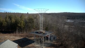
In recent years, shortage of available land and building restrictions have led to more exotic antenna and ground systems, and above-ground, elevated radials are not uncommon today. Unfortunately, the shortages of copper and large increases in copper prices have led to vandalism and thefts of ground system wire and copper.
Ground systems
Sep 1, 2008 12:00 PM, By John Battison, P.E., technical editor, RF
More than copper in the ground
After AM broadcasting commenced, and became a commercially viable industry, a great deal of research took place. This was especially so in the 1930s when the Proceedings of the IRE carried many very detailed reports, confirming that a properly designed and constructed AM ground system involves far more than a copper rod stuck into the ground! They also showed how proper ground system configuration contributes to the efficiency of an antenna system by ensuring an adequate low loss path for the extremely valuable, and costly, antenna current. The fact that ground connections can affect radiation efficiency in another way is sometimes overlooked. Under some conditions, an unusually long wire connection to ground can increase radiation by virtue of adding the radiation from the “ghost” dipole in the ground.

Figure 1. A typical two-tower array layout. The heavy lines between the towers and transmitter are 4″ copper straps.
Figure 1 illustrates a typical two-tower DA ground system. A buried copper strap connects the two tower bases. Around the base of each tower are 120 radials each the same length in feet as the height of the tower. Each radial is spaced 3 degrees around the 360-degree circle. These radials will intersect midway between the two towers, and at this point a buried copper strap (at right angles to the copper strap joining the two towers) is brazed or hard soldered to the intersection points of the radials from the two towers. The intersecting radials need be no longer than the distance from an individual tower to the intersection point.
Ordinary soft lead tin solder should never be used. It disintegrates under earth chemicals and leads to disconnected radials and copper straps, and unexpected low efficiency.
In some cases, especially in very sandy or low conductivity soil, an expanded copper screen may be buried at the base of the tower. Squares of copper screen either 24’x24′ or 48’x48′ are commonly used depending on ground conductivity and transmitter power. These overall dimensions take advantage of the standard width of the copper screen and avoid excessive cutting and connecting.
An alternative to expanded copper ground screens is to bury 120 short, 50′ radials interspersed at 3-degree intervals between the long radials. This also provides greatly improved low conductivity paths for the antenna current’s return. Sometimes the periphery of the ends of these radials is comprised of copper strap forming a circle around the tower base. This is not essential, but it is helpful in low conductivity areas. There is very little to be gained by running a copper strap around the ends of the long radials because normally the current at that point is quite low.
Ground systems
Sep 1, 2008 12:00 PM, By John Battison, P.E., technical editor, RF
From the transmitter
In addition to the buried or mounted transmission lines, a buried copper strap should run from the transmitter to each individual tower. To save money, this strap connection is sometimes omitted. It is a great mistake to rely on the outer conductor of the transmission line to form the return path for the antenna current. A flat copper strap has nominally very little inductance while a round transmission line outer conductor can have appreciable inductance. In some cases, where a separate ground strap connection was not used, instability has been observed. This strap should go directly to the base of the tower and be brazed to the copper straps that come down the four sides of the tower base from the bottom of the base insulator to the origin of each tower’s radial system.
When constructing directional antenna systems, doghouses are decidedly preferable to free-standing metal cases containing ATU equipment. Antenna adjustment is far more comfortable and more quickly completed when there is a protected area in which to work. A few cold and stormy nights very quickly prove this point. It is important to have 120Vac power, and two or three spare pairs of conductors running to the transmitter from the doghouse generally find a use.

Figure 2. The ground strap at the tower base.
Figure 2 shows a doghouse located within the tower fence. A copper strap should be run around the base of the building and connected by another copper strap to the ground ring around the tower base. Radials should originate at this ring, be brazed to this doghouse strap and continue out from the other side of the doghouse. Maintaining continuity is very important in this. Cathodic protection, similar to that used for ships, has been mooted for ground/antenna systems but has not been widely used.
Metal fences around the tower base are far more satisfactory than wooden fences. Wooden fences absorb moisture and can cause changes in tower base operating impedance as the moisture dries and changes the resistance of the fence. The posts of metal fences must be connected to the ground system by means of copper strap. This ensures a stable electrical environment around the tower base and is important for the comfort of people touching the fence.
E-mail Battison at[email protected].