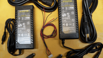
Wall-mounted AC Adaptors, sometimes called wall-warts, have been a standard way of providing electricity to low-power devices since the 1970s, powering everything from clock radios to Wi-Fi routers to cell phone chargers to Alexa to electric shavers and toothbrushes. Station equipment racks are overcrowded with them.
As you know, some 120 VAC outlet strips are made specifically to accommodate these supplies, which typically measure about 2 by 2 by 3 inches.
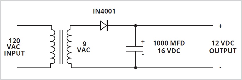
You might not give much thought to what’s inside these apparently simple problem-solvers. They started as convenient devices with a transformer to provide low-voltage AC or a transformer with diodes and capacitor for DC. In either case, they typically provide 3 to 24 volts. Fig. 1 is the schematic of a DC supply.
One real plus for equipment designers is that most of the supplies are UL-listed and have the UL logo when sold in the United States and Canada. Other countries have similar standards.
The idea here is safety. It takes some of the legal liability burden off manufacturers if their product is powered by one of these adapters that isolates the somewhat dangerous 120 VAC from their equipment.
Friend and fellow Radio World contributor Charles “Buc” Fitch authored a piece for John Bisset in the Dec. 29, 2022, Workbench column. He told of replacing a wall power supply with a switching power supply on a Sine Systems RP-8 Relay Panel to improve its reliability.
Switching power supplies
Most power supplies weigh less today but a closer look at their ratings will tell you they are capable of handling more power.
These are “switching” power supplies with dozens of parts that rectify, then chop up the result at 100 kHz or more to create the desired output voltage. Instead of 12 volts at 0.5 amperes (6 watts), one might provide 12 volts at 1 ampere (12 watts) at half the weight.
Switching supplies have DC outputs because they convert the incoming 120 VAC to well-regulated DC. This regulation helps in maintaining the desired output voltage even when the input experiences voltage spikes and brownouts. The outputs provide clean DC without 60 or 120 Hz ripple voltage that older supplies have. By ripple, I mean a slight variation in output voltage that a filter capacitor can’t completely eliminate in older non-switching supplies.
Fig. 2 shows a higher-power switching power supply. I pulled the cover off so you can see the inner workings. Lots of electronics inside. This one uses the universal standard IEC (International Electromechanical Commission) three-wire power cord with ground. As you know, those cables are common to virtually all desktop and server computer systems today, not to mention most rack-mounted broadcast equipment.
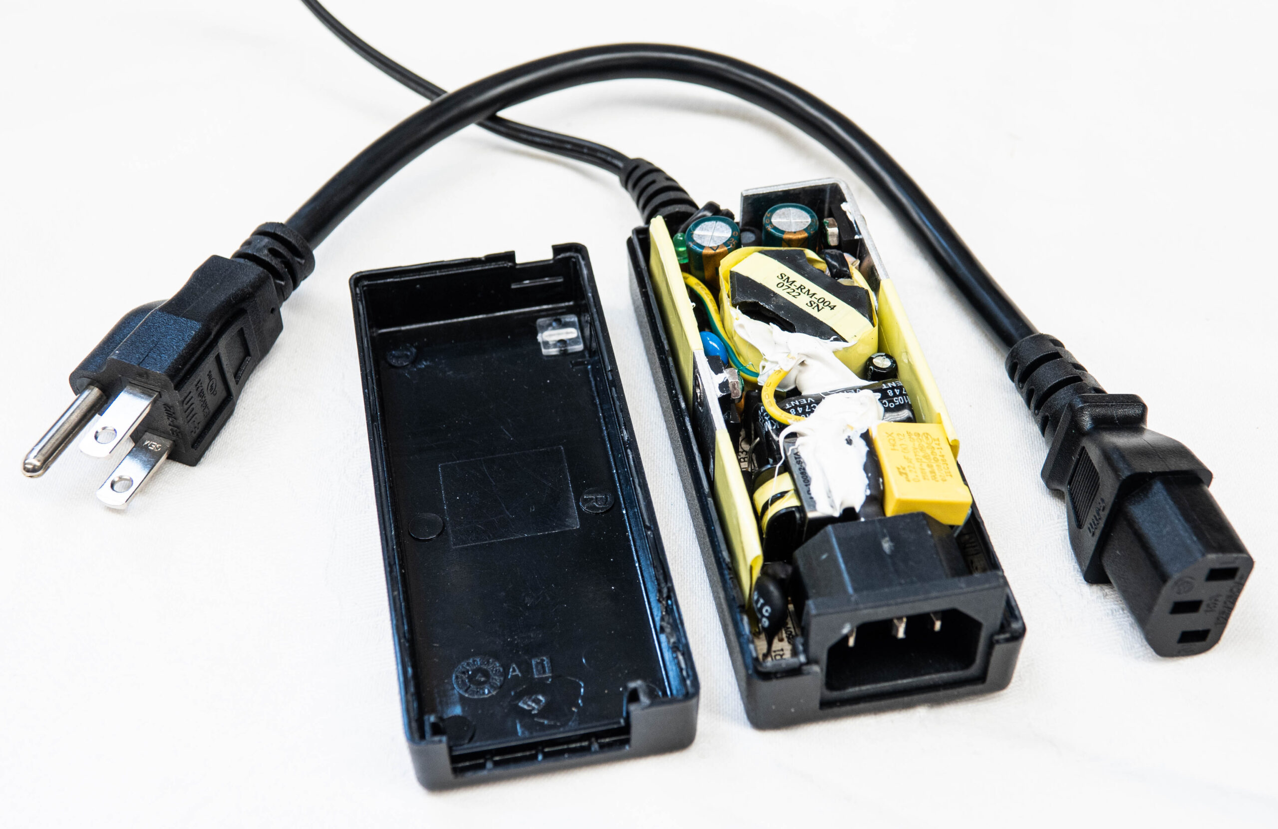
Of special interest to me is the short power cord. These are a real problem-solver when trying to keep excess clutter out equipment racks. I love them!
The enigma
After 60+ years in broadcast engineering and 44 years in business, I am mentoring four radio broadcast engineers. One of them recently called with a problem that was difficult to troubleshoot.
It should have been simple to fix a studio on-air warning light that wouldn’t come on. There was power and the lightbulb was good.
A 120 VAC light outside the studio door was wired correctly. By that I mean 120 VAC was not run through relay contacts in the studio console. Instead, a low-voltage DC control was sent to a Tyco brand SSRT-240D-10 solid-state relay in an electrical box. The relay switches 120 volts to the light.
A measurement of the DC control voltage, at the solid-state relay, confirmed that it was getting more than 20 volts. The relay only needs 3 VDC at about .005 ampere of current to make it operate. That’s a small fraction of a watt. A replacement solid-state relay did not solve the problem.
How could it be?
The clue was the control voltage that should have read closer to 28 volts from the traditional wall-wart unregulated 24 VDC power supply. A multimeter showed it to have more than 10 volts AC at the output too. Ouch, it should have been near zero.
As mentioned, power supplies of this older kind have a small power transformer feeding a rectifier and a capacitor to make DC with only a small amount of ripple voltage. See Fig. 3. An oscilloscope showed 33 volts peak to peak on the DC waveform when it should have been a fraction of a volt. That’s it, the capacitor opened and was no longer able to smooth out the voltage to produce almost pure DC, it was pulsating DC. Electrolytic capacitors are the most common type used in this application. They have a limited (5 to 30 year) lifespan and are bound to fail; it is just a matter of when. Capacitors, as you know, are like batteries. They store energy and release it when a circuit needs it. It might happen 60 or 120 times per second in one of these supplies. The harder they work, the shorter their lifespan. In this case it was 21 years.
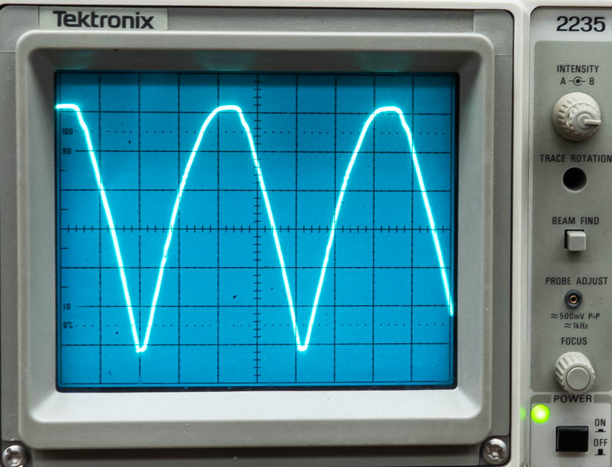
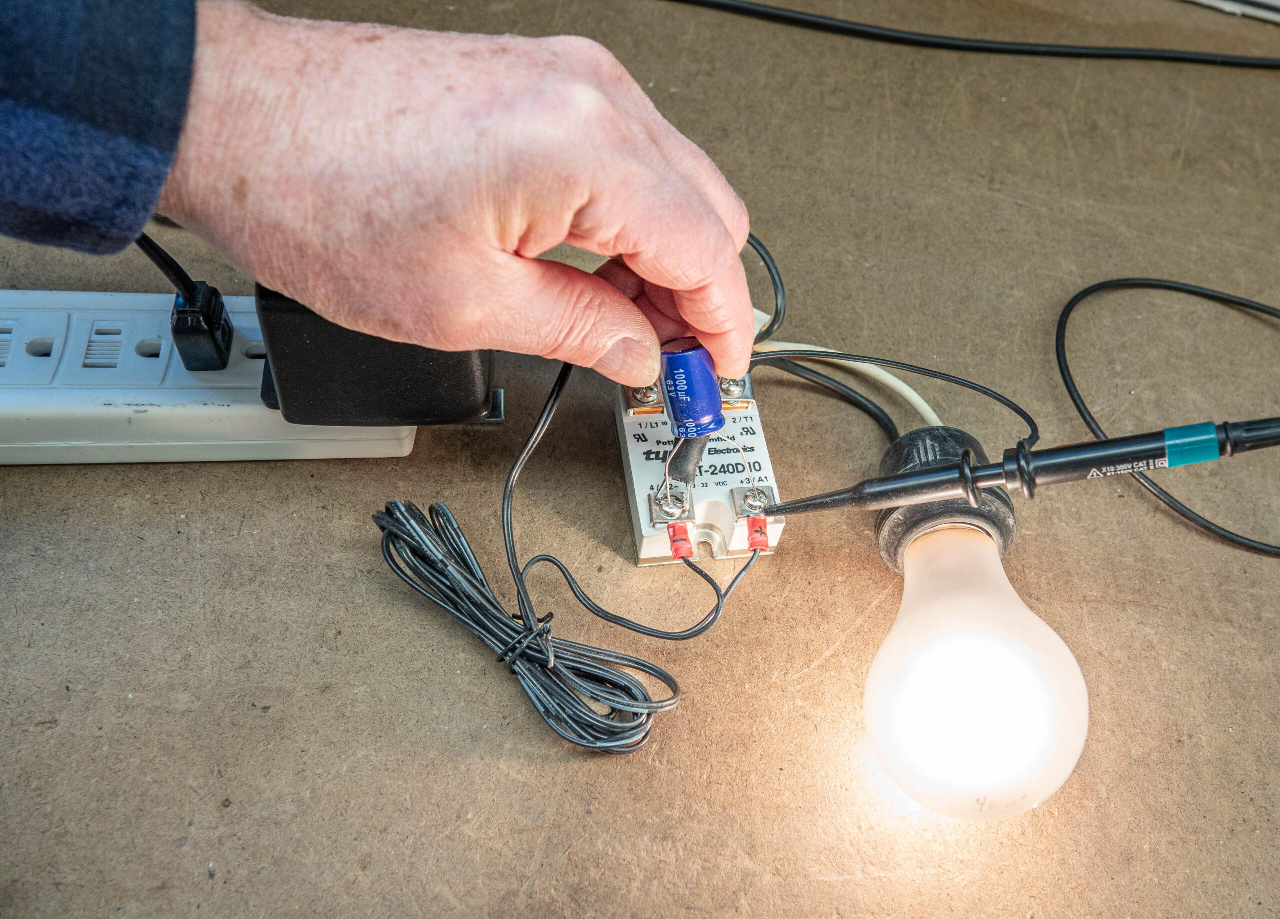
Fig. 4 shows a test setup on a service bench. A 120 volt/40-watt incandescent lamp is the load, simulating the on-air light that is dark. 120 VAC power is supplied via a two-wire power cord to the solid-state relay and the wall-wart in question supplying control voltage to the relay.
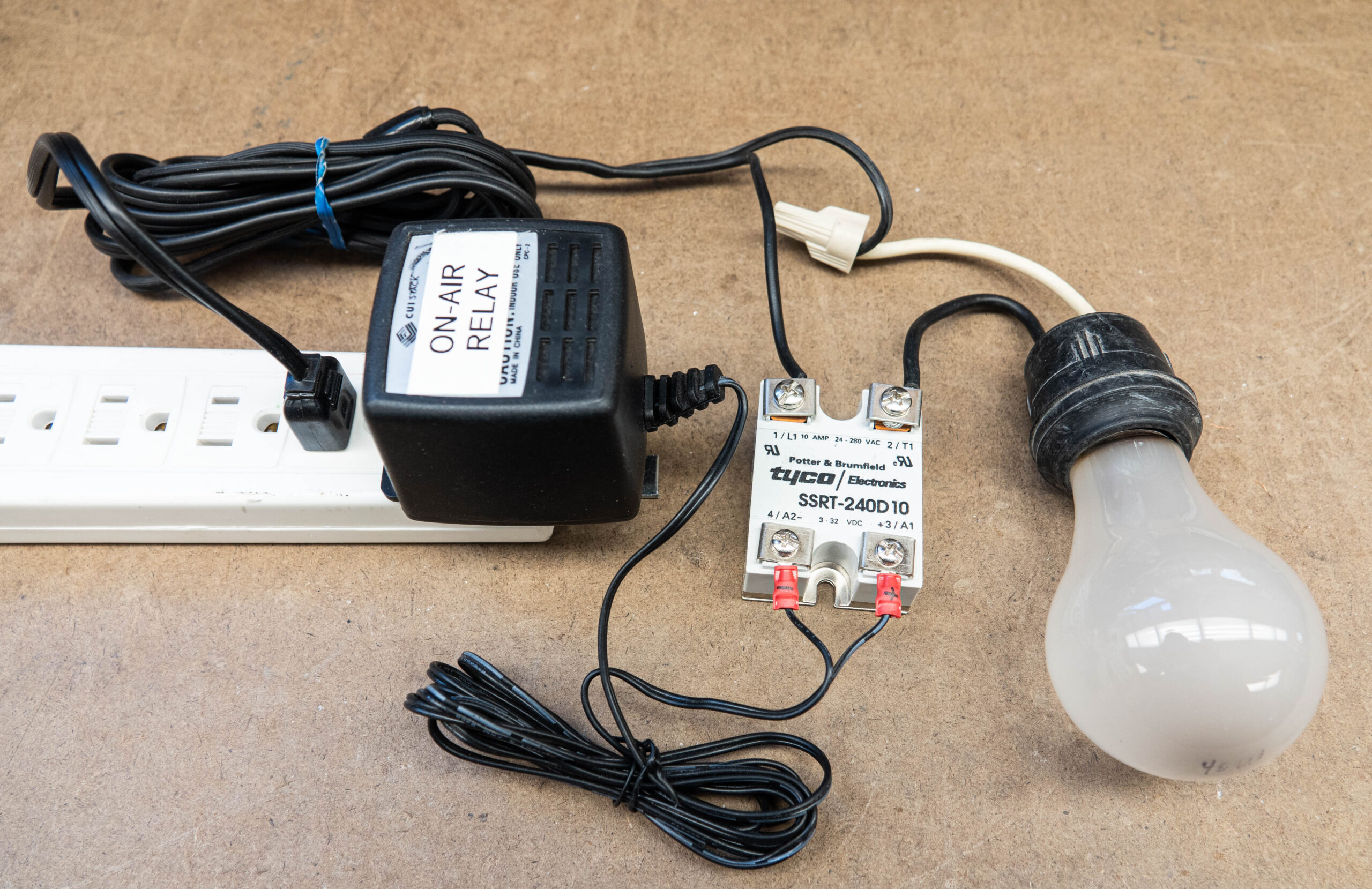
Fig. 5 shows a 1000 mfd capacitor being temporarily connected. The lamp lit at that point.
It is common for audio devices powered by wall-warts to develop a hum problem. Again, it is a failed filter capacitor. The life of capacitors in this service is also limited because it is normal for the power supplies to run a bit warm. The warmer they are, the shorter the life of the capacitor.
Going back to Fig. 4, the photo also shows the power supply is marked to help identify it during troubleshooting. The downside is the label covered the specifications part of the transformer. The lesson is to mark everything in such a way to help everyone in the future.
Sometimes I come across a power supply with a deformed plastic case because the supply ran too hot. Even when one is working, I immediately discard or recycle so it can’t cause problems in the future.
Switching power supplies are now found inside rack-mounted equipment and transmitters. I like the ability of many to switch automatically between 120 and 240 VAC input voltages. What a change from the old days! We are in a plug-n-play world. The downside is that repairing a switching power supply is beyond the ability of most technicians. Repair of a traditional “linear” power supply with a transformer, diodes and capacitor is easy and has been standard fare for most engineers over the years inside of a piece of equipment. No need to throw those out when a one-hour repair plus $10 in parts might solve the problem.
RF noise
Regarding switching power supplies, I recommend you do a quick test at the time of installation.
Tune a portable AM receiver to an open spot on the dial and put it near a power supply. Connect and disconnect the supply from 120 VAC. You may hear noise while the switching power supply is running. If so, that is a problem! Many switching power supplies emit objectionable RF noise. I avoid using them when possible and go for cleaner ones to reduce noise that could contaminate a receive signal, such as off-air monitoring of an AM broadcast station. That could include an EAS monitoring assignment.
Most switching power supplies comply with FCC rules for unintentional RF radiation and/or conducted noise to the power line, but there is a cumulative effect from the millions in use. It is my observation that the noise floor, especially in the AM broadcast band, has risen 10 dB in the past 15 years. The change is accelerating as more and more switching power supplies are put into operation. This is a noise source that spells even more trouble for the AM band!
Ham radio operators are often the first to hear unwanted radio noise because they receive down to the noise level in everyday communications. Hams have found Palomar Engineers at https://palomar-engineers.com/ has a variety of ferrite toroid rings that can keep unwanted RF from traveling down power cables and into the air.
I hope the knowledge related in this article will help you think through making good engineering decisions.
Comment on this or any article. Write to [email protected].