Higher Power IBOC
Jan 1, 2010 12:00 PM, By Doug Irwin, CPBE DRB AMD
Increasing IBOC power is no trivial matter; now is the time to plan.
On Nov. 5, 2009, NPR and Ibiquity Digital jointly submitted to the FCC a proposal for an IBOC power increase. As of this writing, the Commission has not yet acted on the proposal; however, it does appear that an IBOC power increase is imminent. The heart of the proposal is a blanket 6dB increase in IBOC power levels ? but there are a few more details worth looking at. In a nutshell, NPR and Ibiquity are proposing the following changes to the Commission’s rules with respect to IBOC:
- A 6dB blanket power increase (-14dBc) for all stations except super-powered, grandfathered Class B stations. These stations would be limited to the greater of two levels: the current -20dBc level, or at least 10dB below the Class B equivalent power for their height.
- The potential for a power increase to as much as -10dBc, depending upon conditions that limit harmful interference. Stations wishing for more than the 6dB blanket power increase would have to apply to the Commission for permission to do so. NPR has posted an IBOC power calculator online.
The filing also specifies a means by which harmful interference complaints can be resolved by the Commission.
If you currently have a Class-B super-grandfathered station, then this proposed rule change might not affect you at all. Say for example you have a super-power grandfathered Class-B with an ERP of 80kW, while the Class-B equivalent at that same site and antenna height is 8kW. Your current IBOC power would stay the same because 20dB below 80kW is the same as 10dB below 8kW.
Other options
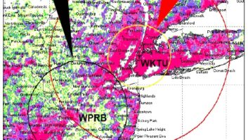
One means by which some stations may be able to exceed the -14dBc limit is by transmitting the IBOC sideband groups in an asymmetrical fashion (currently those sideband groups � one group above the center frequency, and one below � are transmitted with the same amount of power). If a station wishing to increase its overall IBOC power has a first-adjacent channel station below it in frequency that is physically closer than the next station above it in frequency (as illustrated in Figure 1), then it is clear that for a given undesired-to-desired ratio (based strictly upon the distance between the stations) more power could be transmitted in the upper sideband group.

Figure 1. Physical spacing may allow a station to transmit an asymmetrical hybrid signal to achieve the power increase.
A means by which harmful interference complaints can be resolved is also proposed. If, for example, station Y is transmitting IBOC in excess of -20dBc and causes interference inside of station X’s protected service contour, then station X may file a complaint against station Y with the Commission by completing the following steps:
- Station X must include in its complaint at least three interference complaints and evidence of on-going rather than transitory harmful interference inside its own protected contour;
- Station X must document any test measures used to identify the IBOC-related interference, and;
- Station X shall document the extent of the interference.
The FCC will have 90 days after station X’s filing to resolve the complaint. If the FCC does not do so, then station Y will be compelled to lower its IBOC power, in 3dB steps, to as low as the original -20dBc level (but not lower).
— continued on page 2
Higher Power IBOC
Jan 1, 2010 12:00 PM, By Doug Irwin, CPBE DRB AMD
Increasing IBOC power is no trivial matter; now is the time to plan.
Specific situations
If your station is interested in implementing higher power IBOC, then one of two cases must be true already: You currently transmit IBOC and need to consider the implications of raising the power to (at least) -14dBc; or, you are planning on transmitting IBOC for the first time. Let’s assume the former, and take a look at how to increase your current IBOC power first. We’ll look at new systems afterwards.
Perhaps the most common way to transmit IBOC has been by way of a -10dB coupler inserted in the output of the analog transmitter. At least four manufacturers (Dielectric, ERI, Shively and Jampro) make this type of device and assuming they all produce a new version (-4dB injection) then it should be a relatively easy matter to simply swap out the old with the new. The good news here is that the amount of waste heat formerly dumped into the waste load is going to be reduced.
One advantage to this type of coupler (at least at the -10dB injection level) is that there is an exceptional amount of isolation between the analog port and the digital port; a quick look at published specs of the four manufacturers shows 36dB minimum (with good VSWR). The rule of thumb has been -30dB of isolation between the analog and digital ports in an IBOC system (at minimum). In communications with these same manufacturers I was reminded (with respect to higher IBOC power levels) that isolation from the digital ports back in to the analog ports will now also be an important spec to consider, as the chances of generating intermod products in the output of the analog transmitter will now become a distinct possibility. Make sure you consider that specification when choosing a particular brand and/or model of coupler.
Another common method of getting IBOC on the air has been to use an auxiliary antenna. This was a very expedient method in many cases. However, because the new power level is four times that of the old, there isn’t going to a simple way to achieve the increased ERP using the same old antenna. At minimum, you would need a new transmitter; and one that has four times the power capability as the old could be an expensive proposition. You would likely need to upgrade the ac power and air conditioning capability as well. A compromise might be changing the auxiliary antenna to one with more power gain (for example, doubling it) and then buying a new IBOC transmitter that has twice the power output capability as the old one. As in any power upgrade, be certain that the coax in place can handle the additional power; add 5.5dB to the nominal IBOC power to account for the peak-to-average ratio.
Probably the least common method of getting IBOC on the air has been the split-level combining method. This is a system that makes use of the analog transmitter; a combined-amplifier transmitter (meaning the digital and analog signals amplified together) and a high-level combiner that adds the two transmitter outputs together to generate the correct amount of analog and digital power in its output. This system works well especially when the analog transmitter has a lot of power capability, but not the 10 percent headroom necessary when using a -10dB IBOC injector. When increasing the IBOC power level, it will be necessary to derate the analog output level of the combined amplifier; but, depending upon how much headroom is available in the analog-only transmitter, you may be able to make up for that reduced analog relatively easy. The ratio of analog power contributed by the analog-only transmitter to that of the combined-amplifier will increase, so that the output of the combiner has the newly increased IBOC level, with the same analog level as before.
New installations
If you are considering implementing IBOC for the first time for your station, or if you are plan to quadruple the current IBOC power level, it is incumbent upon you to look in to either a combined-amplifier type of transmitter, or an antenna with an IBOC port. If your station uses high-level combining now (by way of the -10dB injector) you’ll likely find the power upgrade relatively inexpensive and painless; however, if you are using space-combining I believe you will find that a new transmitter or antenna will be close in cost to the upgrades of the old system.
Let’s consider a new antenna first. All four of the major antenna manufacturers offer at least one antenna model with both analog and IBOC input ports. In the case of Jampro, it’s the JSHD; for ERI, it’s the Lynx. For Dielectric, it’s the HDR series of interleaved elements; Shively offers an interleaved antenna as well, such as its 6813.
One advantage to using the dual-input antenna type is that the characteristics with respect to the radiation pattern will match between analog and digital. The analog power doesn’t change; simply feed the digital port with enough TPO to make the -14dBc ERP requirement. As an added bonus, the digital port can become a backup input for the analog transmission (albeit lower power). Ask any potential vendors about the digital-to-analog as well as the analog-to-digital port isolation.
As I wrote earlier, the rule of thumb has been a minimum of 30dB of isolation between ports. You could add isolators to the digital transmission line to improve the isolation from the analog port, but the other direction could be more of a problem. I’ve been assured by each of the four vendors mentioned that the digital input ports to their antennas will handle -10dBc, so obviously -14dBc will not be an issue.
— continued on page 3
Higher Power IBOC
Jan 1, 2010 12:00 PM, By Doug Irwin, CPBE DRB AMD
Increasing IBOC power is no trivial matter; now is the time to plan.
Perhaps you are very happy with the antenna you already have, but would consider replacing your current analog transmitter with a combined-amplifier type. Fortunately a lot of transmitter development has gone on over the last five years and buying this type of transmitter is easier now than it was way back when.
Nautel offers an extensive line of all solid-state combined-amplifier style transmitters as the NV Series. This line extends from the NV3.5, with an analog power rating of 2,700W of analog at the -14dBc IBOC level, up through the NV80, which will make 57,600W of analog in the -14dBc mode. The Nautel Power Boost is a peak-to-average-power reduction technique that Nautel estimates will effectively boost the analog power capability of the NV Series transmitters by about 1.3dB.

Nautel offers an Excel file tool to determine if a transmitter is capable of delivering the increased digital power, and what steps need to be taken to accommodate the increase.
Harris has been busy working on its IBOC transmission technology as well. It offers three lines: the ZX series (500W up to 5kW); the Z/HD+ series (4kW up to 32kW); and the vacuum-tube series that includes the HT/HD+ and HPX20 through HPX 80. Harris is also working on its version of peak-to-average power reduction, and will introduce it at the 2010 NAB Show. Harris expects to gain about 25 percent more analog power from its combined amplifier types when this algorithm is fully implemented.
Harris
XmtrAnalog and Digital Common Amplification
TPO in Watts -20dBc-14dBc-10dBc ComADComADComAD ZX50041340943553411424021822 ZX100082581787106832748043644 ZX35002800277228241023179216291481148 ZX500041254084413550341413624002182218 Z12HD+60005941593975382315231952905290 Z16HD+80007921795300509720342603873387 Z32HD+1600015842158106001019440685207745775 HT/HD+2500024752248143001375354791008273827 HPX202100020792208170001634965115000136361364 HPX403150031188312195002146153917000154551545
Transmitter power deratings for some Harris transmitters at increased digital sideband powers.
At the time of this writing, Broadcast Electronics is in the process of evaluating and optimizing its transmitter line for proposed IBOC power increase.
Because the proposed IBOC power increase hasn’t yet been approved by the FCC, it may be a little early to budget for transmission facility upgrades � but at the very least you should be in the planning stage. Increasing IBOC power by even four-fold is no trivial matter, and it could affect the entire infrastructure of your transmission facility. If you believe that terrestrial broadcasting has a continuing future, as I do, then now is the time to plan for it.
Irwin is transmission systems supervisor for Clear Channel NYC and chief engineer of WKTU, New York. Contact him at[email protected].