WCFB rebuilds: Optimizing the Antenna
Jun 1, 2009 12:00 PM, By Matt Leland
After the dust had settled on getting WCFB on air at a temporary site, the task of selecting a new antenna for the permanent installation began. Cox Radio brought its regional and corporate engineering resources together to address the task. Steve Fluker was joined by Roz Clark, Charles Kinney and Sterling Davis to take a thorough look at the entire site reconstruction. Because Dielectric had manufactured the previous antenna in 2002, a DCR-M8 quadrapole, we had a record of the pattern that was created at that time to use as a baseline as well as an increase in the station’s market ratings Cox wanted to maintain. The difference this time was that the antenna would be mounted on a new tower rather than an existing one. With a new tower, a clean slate, the tower geometry could be integrated into the new antenna design rather than working around an existing structure. Before heading blindly off in that direction, other options were weighed. Dielectric and a competitor produced patterns and coverage maps for variety of panel and side-mounted antenna models on towers of varying face-widths. Ultimately, the DCR-M quadrapole was selected for the job. Although Cox Radio generally puts good engineering before capital cost, it didn’t hurt the quadrapole was significantly less money than a panel antenna.
Because Stainless was selected to build the tower and Dielectric the antenna, we worked together as a team to integrate the two products. Initial testing for the tower/antenna configuration was made using scale models of the antenna and towers to determine the best combination of the two. Don Doty of Stainless, Steve Fluker of Cox Radio, and his consultant, Dean Sargent, came to Dielectric to work with our engineers during the testing so that we could have everyone’s input on how our antenna affected the tower design and vice versa as well as meeting the customers’ goal for the desired azimuth pattern.
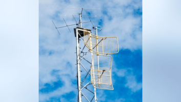
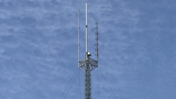
From the results of the scale pattern testing, the full-scale tower and antenna were designed and built. The tower was designed so that the same panel configuration replicated at even intervals with the antenna bays so that the azimuth pattern produced at each of the eight bays was consistent. The tower sections were shipped to Dielectric where we mounted the full scale antenna on them. We then stood up the entire eight-bay array and tower on a pattern turntable and re-ran the pattern to verify that it replicated the scale model tests. The photo [DSCN0186.jpg] shows a single parasitic element used behind each bay. In keeping with FCC rules for non-directional antennas, the parasitic does not increase the gain of the antenna. This was a great team effort, and produced great results. Thank you to all who contributed.
Leland is the sales manager, FM systems at Dielectric Communications, Raymond, ME.