Gather ’round, children. I know it’s way past your bedtime, but Grandpa Steve is not yet finished talking about the history of wire and cable. But count your blessings. At least we’re into the 20th century.
So where were we before we were so rudely interrupted?
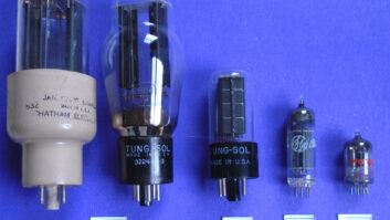
Oh, yes. We were talking about the telephone and the invention and improvement of the triode vacuum tube, the first true amplifier, which made long-distance telephony possible.
The first cross-continent call from San Francisco to New York occurred on Jan. 25, 1915, at the San Francisco Panama-Pacific International Exposition, celebrating the opening of the Panama Canal. My grandparents were both there. I wonder if they saw the new “cross-country” telephone?
The call was from San Francisco, made by Theodore N. Vail (1845-1920), one of Bell’s original partners, to the great man himself, Alexander Graham Bell. Thomas M. Watson, Bell’s original assistant at the invention of the phone, also made a call from San Francisco to President Woodrow Wilson in Washington.
By 1915, the nation had 11 million phones in service.
In the lab
The World War helped the market for wire and cable, as it did for many technologies. The progression of radio also was a major boost, although transmitted frequencies were still low, so the performance of the cable was not a major obstacle.
Partway through the war, planners realized that Germany and its allies could cut off the Allies’ supply of rubber with a few ships blockading Central and South America. This would affect the supply of insulated wire and tires for military cars and trucks.
Luckily, such a blockade was never attempted. But this “scare” started the search for new insulations, a topic we will revisit.
Engineers working for the Bell System realized they needed a research arm to answer the many questions about communications, wire and cable. In 1907, Vail, soon to be president of AT&T, combined the engineering departments of AT&T and Western Electric.
By 1925, Bell Labs had become a major force in scientific research.
One of the key problems with wire and cable was how to measure it. Of course, you could always test a short section in a laboratory; but the real world contained millions of miles of cable.
Until the 1920s, the loss on a pair of telephone wires was measured by a unit known as the “mile of standard cable.” This unit of measure was used until 1923, when the “transmission unit” was adopted. The new unit was defined as 10 times the common logarithm of the ratio between two levels. Use of logarithms allowed the easy expression of wide differences in levels. In 1924, it was proposed that this “transmission unit” be renamed a “bel.”
However, the “bel” did not convert easily to units in use in Europe. One-tenth of a “bel” was easier to convert, so the unit was changed to one-tenth bel, or “decibel.” This was communicated to the Bell System engineers by W. H. Martin in January of 1929. A copy of this very memo was given to me by my friend Bill Ruck.
Combination effect
One of the first major Bell Labs projects was to understand the nature of cable. With millions of phones in service, wiring was getting out of hand. And the wiring between central offices was becoming an even bigger problem. The telegraph had multi-level and multi-tone systems that allowed multiple messages to be sent down one line. Why couldn’t this be done for the telephone?
Standard twisted pairs had many disadvantages. Resistance, capacitance and inductance had been understood since the mid-1800s. Engineers soon realized that the combination of these effects had a profound effect on cables, especially at higher frequencies.
These frequencies, the “unused” territory of bandwidth on a cable, interested Bell Labs. If one wanted to send multiple voices down cables, it would only happen at higher and higher frequencies. So these frequencies, and the effect they had on a cable, had to be understood. The combined effect of resistance, capacitance and inductance was termed impedance, described as “the total opposition to current flow.”
Twisted pairs, comprising nothing more than wires loosely twisted together, had serious problems at high frequencies above 100 kHz. The space between the wires would change when the cable was flexed. This change in conductor-to-conductor spacing affected capacitance and therefore varied the impedance of the cable. Pairs with uneven insulation or insulation that varied in quality also affected the stability of impedance. These twisted pairs were poor choices for high-frequency applications.
Two wires, one axis
How do you make two conductors that are physically locked together so that the dimensions are stable? If dimensions are stable, impedance is stable; and this construction would be good for high-frequency applications, the place Bell Labs wanted to play.
So we come to one of those moments in history in which an idea comes about, driven simply by the need to exist, one that seems to have no precedent based on previous work, a true invention.
The answer was furnished by two unsung heroes of the cable world, Lloyd Espenschied and Herman Affel of Bell Labs. On May 23, 1929
, they hit on the idea of putting one wire inside the other wire. This still sounds impossible. Imagine how it must have sounded in 1929.
Having one conductor inside the other meant that they shared the same axis, so this construction was called coaxial cable. This design demonstrated extremely stable impedance and was excellent at high frequencies.
There was really only question left: what impedance should this coaxial cable be? For now we’re talking about high frequencies (in the megahertz!) in which one must match the source and destination devices with a cable of the correct impedance. What impedance would work best?
This turned into three questions. What cable impedance would give the lowest attenuation or signal loss? What cable impedance could handle the most power (watts)? What cable impedance could handle high voltage?
They built hundreds of cables starting with the same center conductor and measured various parameters on each one. What they found surprised them, for the appropriate impedances for each requirement were completely different.
Do you know what those numbers were? I bet you don’t. Tune in for the next exciting episode!
Earlier installments in this series on the history of wire are at www.rwonline.com.
Steve Lampen’s latest book, “The Audio-Video Cable Installers Pocket Guide,” is published by McGraw-Hill.