12 Volt Challenge Question posed in the last issue
(Exam level: CBT)
You have an immediate need to create 12 volts of AC for a power tube filament using two available, identical 6 volt secondary transformers. Referred to the drawing, how would you connect them together to make 12 volts from a 240 volt AC supply?

a. There is no combination that will work because the cores are common.
b. A tied to S1, H tied to S2, B & C tied together, D & E tied together, F & G tied together, J & K tied together and then connect the 12 volt load across I & L
c. A, C, E & H tied to S1; B, D, F & H tied to S2; J & K tied together and then connect the 12 volt load to I & K
d. A & E tied to S1, D & H tied to S2, B & C tied together, F & G tied together, J & K tied together and then connect the 12 volt load across I & L
e. A & E tied to S1, D & H tied to S2, B & C tied together, F & G tied together, J & L tied together and then connect the 12 volt load across I & K
The given transformers limit the output configuration to a series arrangement in order to develop the required 12 VAC. The correct answer is the final one, (e).
Probably your first reaction would be one of incredulity; isn’t the answer (d)?
Both the writer and our distinguished editor thought that our readers were getting a little complacent with the very organized, linear “Spockian logic” of the question-and-answer normally found here in the SBE Certification Corner. So a little curve has been introduced this episode to make a most important point about the topic, and if you got the answer correct, kudos to you.
Transformers allow us to change AC voltages in order to convert from a typical supply voltage to a desired working voltage within equipment.

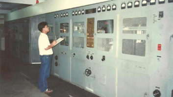
A home-made panel using a set of standard transformers interconnected to create a high-current filament supply. When combining transformer voltages (or any voltage actually), polarity is important. In AC circuits polarity is really the relationships between the phases of the voltages involved. Dots are used to indicate these relationships in drawings where the polarity phasing of transformer windings is important. If you introduce a positive swing into the lead marked with a dot on the primary, secondary leads marked with a dot will similarly experience a positive polarity.
Notice in the drawing that the phasing dots on the secondaries are at leads I and L. If the primaries of the two transformers are configured and the input voltage applied identically, then the voltage at the secondaries will be identical hence “in phase” at leads I and L.
Intuitively, the way the drawing is laid out, one might think the relationships described in (d) are correct but the dots set the actual phasing.
Similar to stringing batteries together, series sources properly polarized (plus to minus in batteries) will add. If connected in series but out-of-phase, the source voltages will subtract.
Although in answer (d) the primaries are configured properly such that with 240 volts primary input each of the two secondaries will have 6 volts on them, the secondary connections as described would essentially cancel the voltage between I and L as the connections are out of phase. Thus (d) is incorrect.
MIX AND MATCH
Let’s look at the primaries for a moment and address a second concept: conversion ratio.
This problem is a good example of how combining a number of standard transformers can create a custom voltage conversion. Transformers designed for AC conversion can maintain, increase or decrease the voltage between primary and secondary. The relationship is set by the “turns ratio,” which is the ratio of coil winds in the primary to those in the secondary.
The ratio in each of the 120 volt primaries to the secondary in these transformers is 20:1. There are 20 winds on the primary to one wind on the secondary. As a practical matter in the design of an efficient transformer, the primary could be 60 winds and the secondary three but the ratio would remain the same. The secondary voltage is the primary voltage divided by the turns ratio. In this example, 120 VAC on the primary divided by 20 equals 6 VAC on the secondary of each of the transformers.
Paralleling the primaries in phase maintains that 20:1 ratio so that 120 volts applied produces 6 volts on the secondary. When a pair of 120 volt primaries are placed in series the ratio increases to 40:1 and thus 240 volts input is needed to produce 6 volts on the secondary.
Answer (b) is incorrect as we are putting all four of the primary windings in series, essentially creating a 480 volt primary. We would need 480 volts on the primary to achieve 6 volts on each of the secondaries and since we only have 240 volts available, that 6 volts could only be 3 volts.

The high-voltage transformer taps are set to adjust the amplifier high-voltage supply based on the provided utility voltage. The taps can be set to either add or subtract from nominal supply voltage as required. Answer (c) is incorrect as the primary configuration would present a short to the 240 volt AC source because both legs feed lead H.
Answer (a) is incorrect on its face as the cores of the two transformers are separate.
CLOSE ENCOUNTERS OF THE TURNS RATIO KIND
For most of us broadcast types, the need to understand transformers comes when we must set or adjust taps in our transmitter high-voltage supply on the primary of the high-voltage transformer. Because of the various supply voltages available from the utility, or when your site has a continuous high or low line voltage from the nominal, we sometimes need to make these adjustments manually.
Normally two sets of tap adjustments are made available in your typical 1 kW tube-type AM transmitter such as the one shown in the schematic from the classic CCA (see RW article on this rig at rwonline.com/article/2806).
If your site had single-phase power with a nominal 240 volts on the line, you would set the taps as shown with one phase line on the 230 volt tap and the other phase line on the +10 volt tap.
If your site had a three-phase wye supply (120 volts phase to neutral and 208 volts phase to phase), then you would set one phase line to the 208 volt tap and the other to the 0 (zero) tap.
What we’re doing here in each of these cases is adjusting the turns ratio such that we obtain the desired 1700 volts on the hi-voltage secondary.
The nature of this question brings us to a general comment on technical test-taking and question solving. There are two ways to approach this genre of question: work to the solution or work from the answers.
If you know for certain how to work the problem, solving for the solution and then looking for the correct answer is probably best. If you do not completely understand the question or have a full grasp on the concepts and issues involved, working from the answers usually will increase the probability of a correct response.
***
For the next issue, a CBT-level question:
What are the advantages of a solid-state bridge rectifier over a solid-state full-wave rectifier?
a. Reduced peak inverse voltage rating requirements for the rectifiers
b. Better utilization of the power-handling capacity of the supply transformer
c. Reduced voltage drop
d. b. & c. above
e. a. & b. above
The deadline for signing up for the next cycle of SBE Certification exams is Sept. 18 for testing that will be given between Nov. 6 and 16 in the local SBE chapters.
Buc Fitch, P.E., CPBE, AMD, is a frequent contributor to Radio World. Missed some SBE Certification Corners or want to review them for your next exam? See the “Certification” tab under Columns atradioworld.com.